Introduction
This article outlines the procedure to set up EIP communications between a CJ2M and QX-870 Barcode Scanner: receiving barcode data, clearing data, sending explicit trigger commands. This Guide is also applicable for QX-830, simply swap the EDS file when installing.
Pre-Requisites
Ethernet/IP Setup guide using Network Configurator
Further Reading
Procedure
Step 1 - Hardware Setup
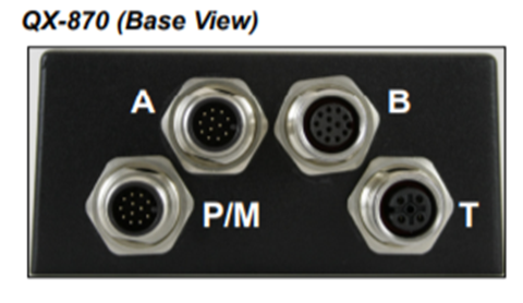
Connect port P/M of the QX-870 to power and Port B to the Ethernet Switch along with the CJ2M and PC.
Step 2 - QX-870 Configuration
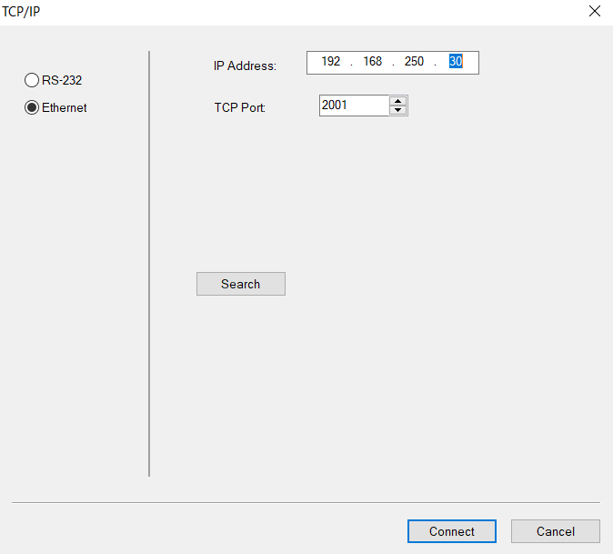
Load the ESP and Device Discovery Utility software from https://www.microscan.com/en-us/support/download-center. Once installed use the Device Discovery Utility to find the IP address of the QX-870 and change it to the desired value. This example will use 192.168.250.30 for the QX-870 IP address and 192.168.250.1 for the CJ2M IP Address. Once the IP address has been found, open the ESP software, select QX-870 from the options and connect to the device via ethernet.
Note: Occasionally the search option will not discover the QX-870. If this is the case, click connect to establish a connection and the bottom right tab should turn green. Otherwise, ensure TCP port is correct (2001 is default).
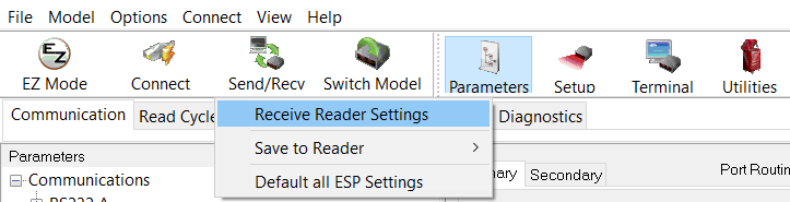
Click on the App Mode icon in the top left corner to open the following page. Now click on the Send/Recv Icon and transfer the Scanner settings to the PC:
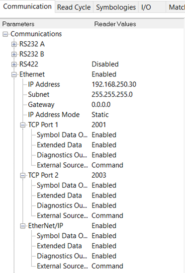
Open the Ethernet and Ethernet/IP settings under the Communications tab and set as below:
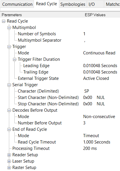
Move to the Read Cycle tab and set as below. This example uses continuous read which can be changed per the application.
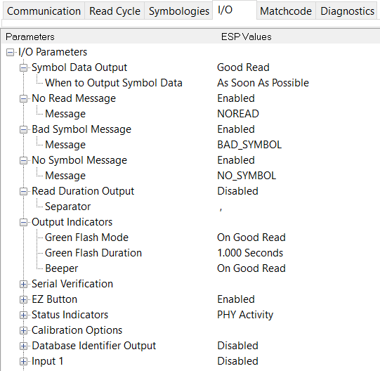
Move to the I/O tab and set as below.
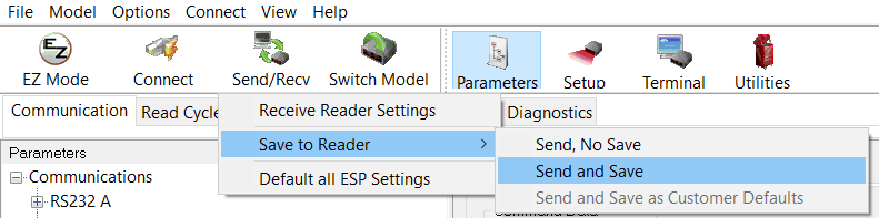
Save data to Scanner using the Send/Recv icon:
Step 3 - Network Configurator
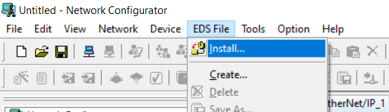
Open network configurator and click on EDS File from the Toolbar and install the QX-870 EDS file
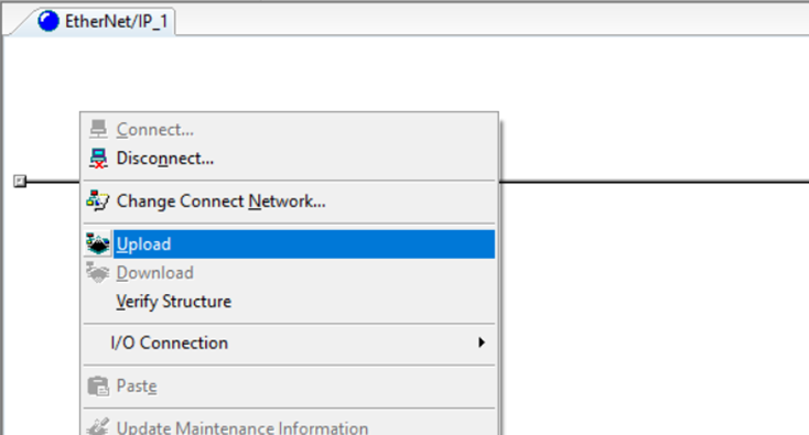
Once the EDS file is installed right click under the Ethernet/IP_1 tab, click connect and follow the prompts. The icon should turn blue after connection:
Once connected, right click again and select upload, the software should detect the CJ2M and QX-870 automatically
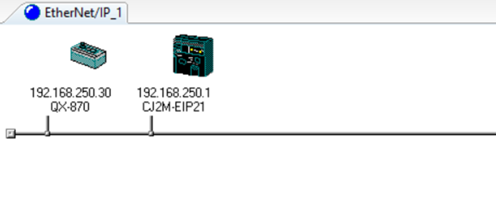
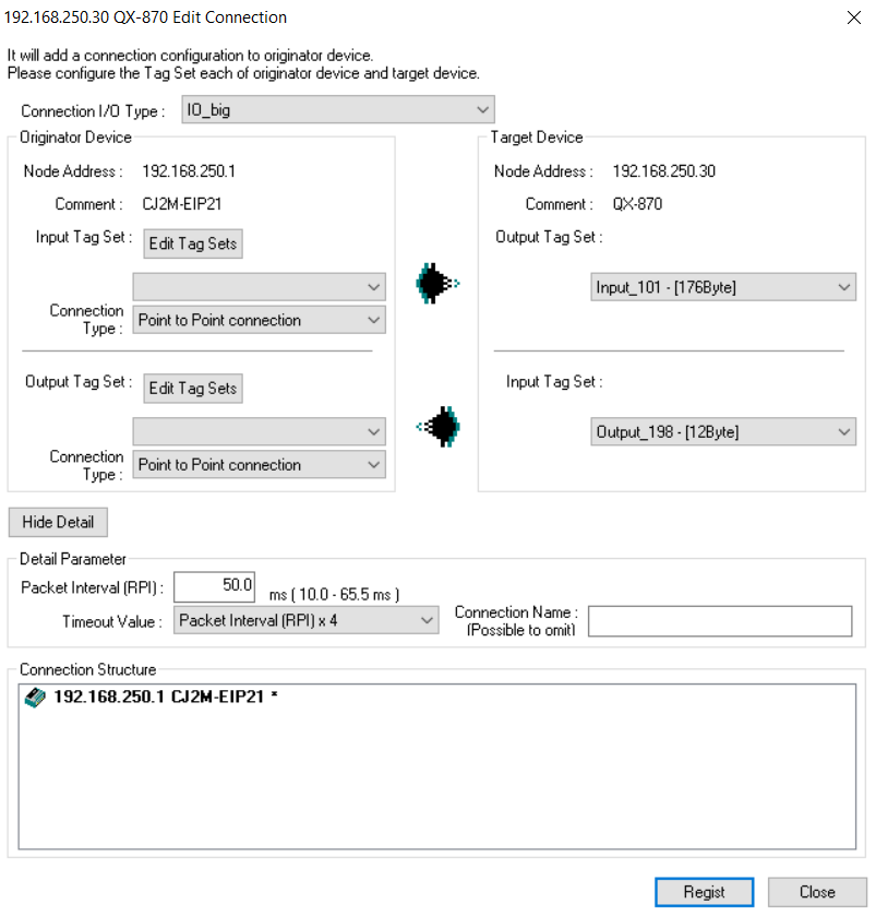
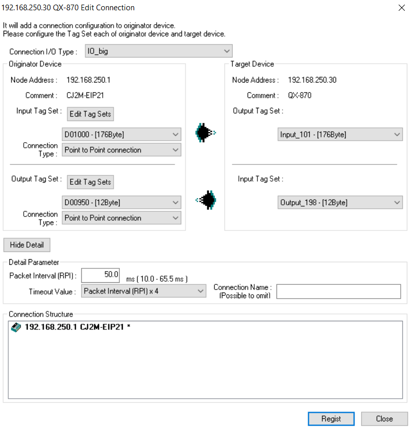
Drag the QX-870 icon onto the CJ2M to establish an EIP connection between the two devices. A pop-up will open allowing you to set input/output Data tags. First, select IO_big in the top option, then select Input_101 and Output_198 in the target device.
Now it is necessary to create the input/output tags for the CJ2M. With C series PLC’s it is possible to simply declare memory areas as the tag name. Firstly, for the Input Tag Set, select Edit Tag Sets -> Edit Tags -> New and set the name to D1000 and size to 176 Bytes. The name of this Tag Set is also its location in memory (Data memory 1000). Click Register -> Close -> Ok until back to the first pop-up.
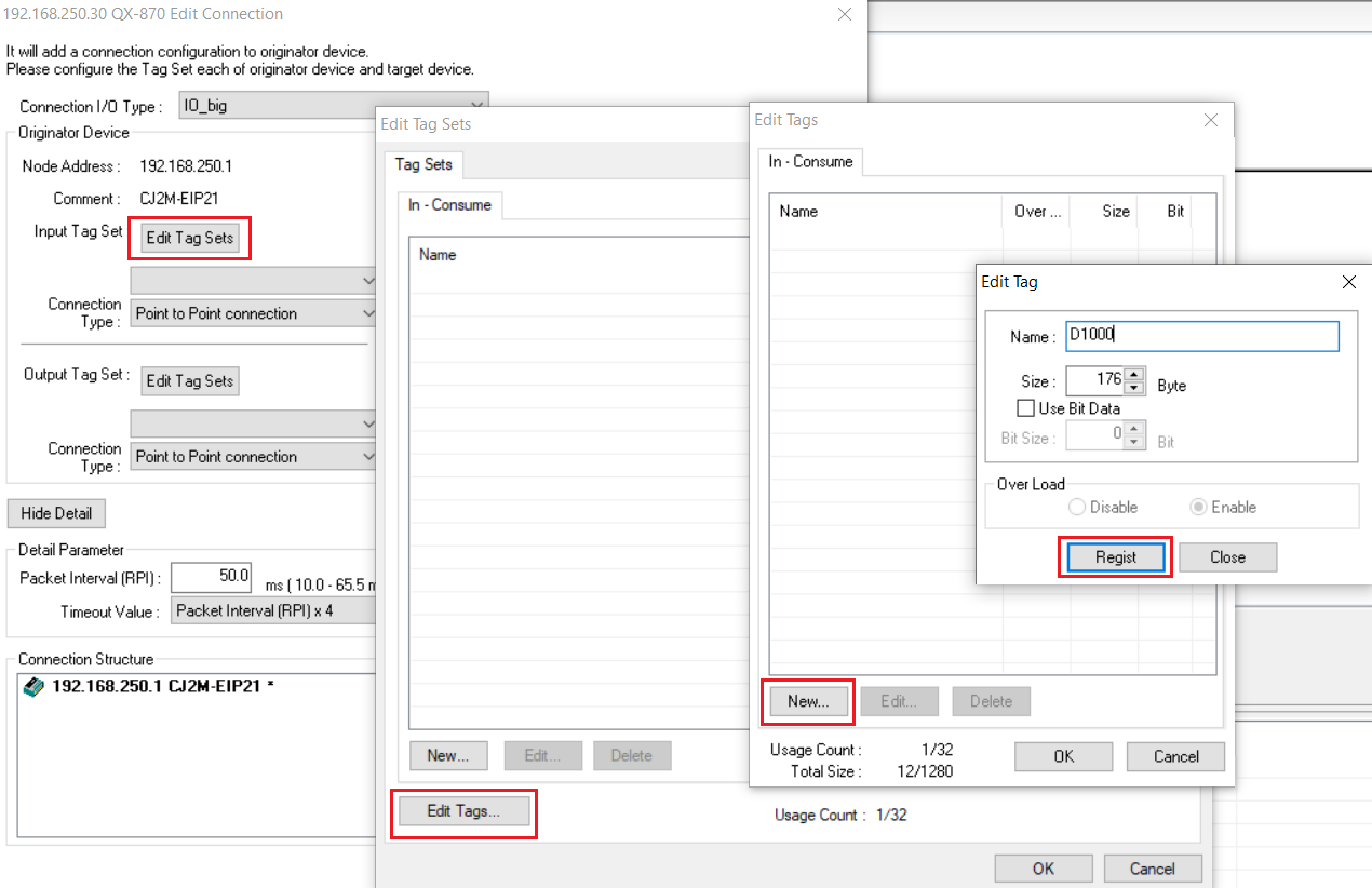
Apply the same procedure for the Output Tag Set but change the name to D950 and the size to 12 Bytes.
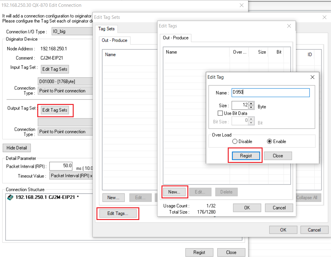
Select both tag sets in the drop-down menu underneath the Edit Tag Sets option so that the final result is as below. Then click register.
Download the parameters to the devices by right clicking as before and selecting Download. Ensure the CJ2M is in Program Mode before downloading.
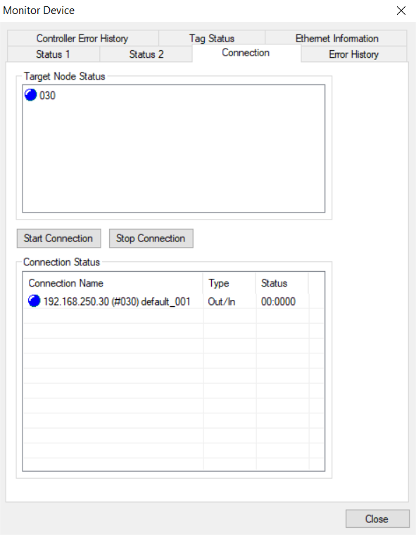
The two devices are now connected via implicit Ethernet/IP. To confirm this connection, right click on the CJ2M icon and select Monitor. The following pop-up will be displayed, navigate to the Connection tab and confirm that the icon's are blue, signifying a correct connection.
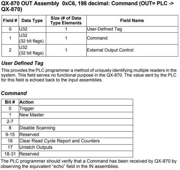
To view the barcode data in the PLC memory, first connect to the CJ2M via CX-Programmer. Then double-click on Memory in the workspace section and then monitor Data Memory 1000. It is best to change the view to ascii to properly see the barcode data:
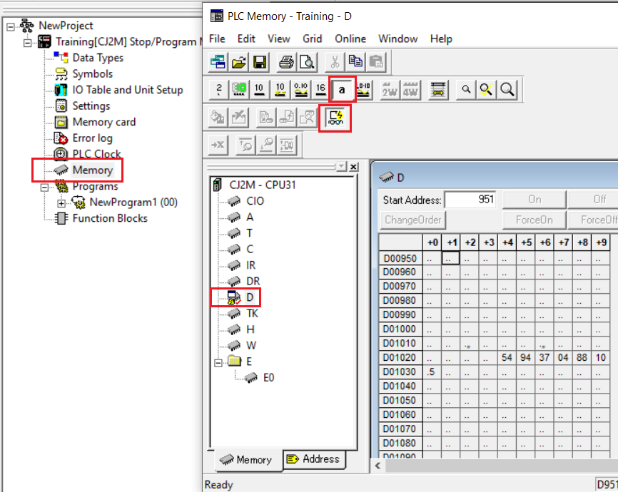
The Barcode data will likely be Byte-swapped. The above example is reading a barcode 4549734088015. Data movement instructions will need to be used in Ladder code in order to correctly orientate the bytes. Please note, as implicit EIP refreshes every 50ms it will not be possible to manipulate this data as it will instantly be refreshed. In order to manipulate the data, use a MOV(021) instruction to copy the data to another memory area.
Note: The first 4 bytes of the Output Tag are unused and mirrored in the first 4 bytes of the Input Tag. This can be used to check connection between the QX-870 and CJ2M.
Step 4 - Sending Commands to QX-870
The middle four bytes of the Output Tag can be used to send commands to the QX-870. The below snippet is taken from the QX-870 user manual, Appendix J.
Clearing Data:
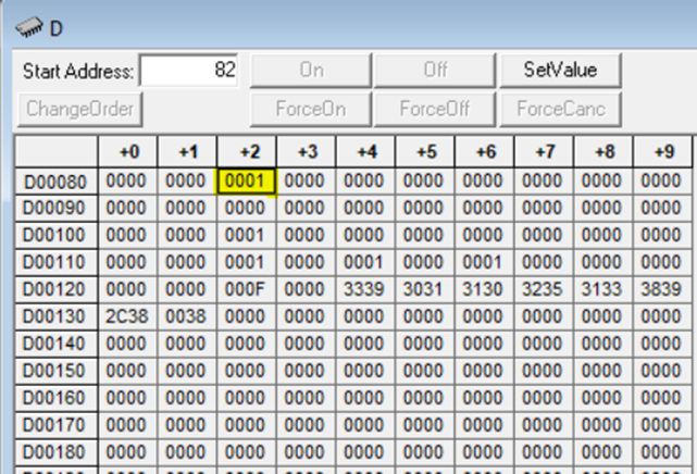
When the QX-870 reads a barcode, it will output the barcode to the PLC continuously until another barcode is scanned. In some applications it may be useful to clear this data that the QX-870 sends to the PLC. This can be done by setting the command bit #16. In the example below, the 12-byte Output Tag starts at memory area D80, and Input Tag starts at D90. The barcode data is received:
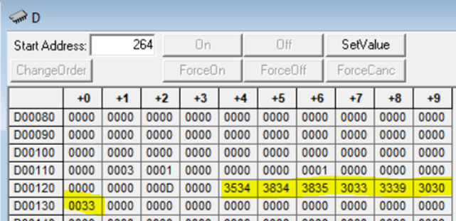
And then once this data is transferred to another memory area for manipulation, the incoming scanner data is reset by setting command bit #16 to 1. This can be done in ladder code by using the MOV(021) instruction.
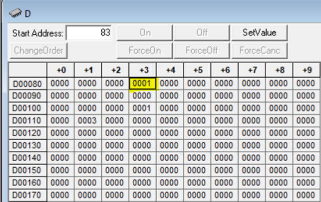
Once the barcode data has been cleared, return command bit #16 to zero and when the scanner successfully scans another barcode the data will reappear.
Sending Explicit Trigger Commands:
Rather than using Continuous Read Mode it is possible to send an explicit command to trigger the barcode scanner. The Trigger Mode in the ESP software must be set to Serial, Edge or Level for explicit commands. Once this has been saved on the Scanner, turn Command bit #0 to 1. On a rising edge the barcode scanner will trigger once. If you are using this mode you may need to re-trigger multiple times in case the Scanner doesn’t read the barcode on the first attempt.
Note: because implicit EIP uses a 50ms refresh time there can be up to a 50ms variation between when the command is sent and when the scanner triggers.
Please refer to the QX-870 user manual for more information on the Input/Output tags, particularly Appendix J.