RX2 inverters offer a range of logic input and output options for control purposes. One of the more common are the multi-function input and output terminals.
These multi-function terminals are favoured due to their adaptability and ease of integrating them into an existing logical control system, such as a PLC. However, the terminals must be set up and wired correctly, so as to ensure that the RX2 inverter receives the signals that it is expecting.
This guide will show a user how to select between Sinking (NPN) and Sourcing (PNP) logic, as well as how the configure wiring for using the internal or an external power supply.
Sinking or Sourcing?
Towards the top of the control circuit terminal, there are six switches. For configuring the input and output wiring, switches 5 and 6 (SW5 and SW6 respectively), are important.
SW6 determines whether the RX2 inverter is expecting Sinking (NPN) or Sourcing (PNP) signals. Please set this switch to SRC for Sourcing, or SINK for Sinking.
SW5 determines whether the RX2 will use its internal power supply or an external power supply. Please set this switch to IN for the internal power supply, or EX for an external power supply.
Input Wiring Configurations
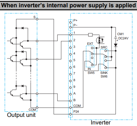
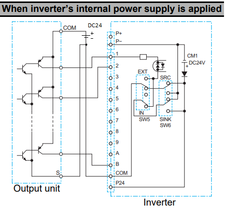
Sinking (NPN) Logic for Internal Power Supply
Connect the positive voltage input of the output unit (S) to P24. Connect the COM of the output unit to the COM terminal of the inverter.
Connect each signal output from the output unit to terminals 1 through B, depending on your required inputs.
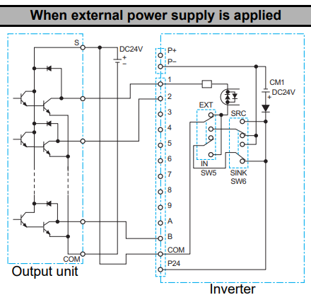
Sinking (NPN) Logic for External Power Supply
Connect the positive voltage input of the output unit (S) to the COM terminal of the inverter, and to the positive voltage terminal of the power supply. Connect the COM of the output unit to the negative or neutral voltage terminal of the power supply.
Connect each signal output from the output unit to terminals 1 through B, depending on your required inputs.
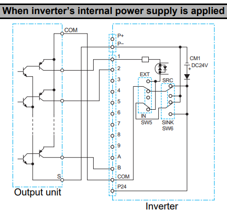
Sourcing (PNP) Logic for Internal Power Supply
Connect the voltage input of the output unit (S) to P-. Connect the COM of the output unit to the COM terminal of the inverter.
Connect each signal output from the output unit to terminals 1 through B, depending on your required inputs.
Sourcing (PNP) Logic for External Power Supply
Connect the voltage input of the output unit (S) to the neutral voltage terminal of the power supply, and the COM terminal of the inverter. Connect the COM of the output unit to the positive voltage terminal of the power supply.
Connect each signal output from the output unit to terminals 1 through B, depending on your required inputs.
Output Wiring Configurations
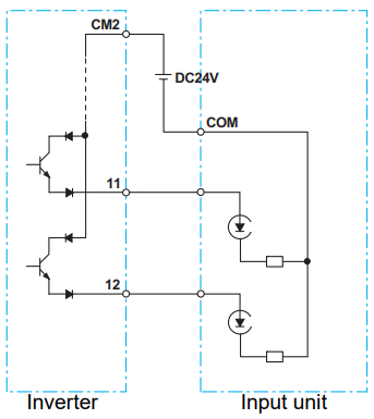
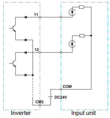
Sinking (NPN) Logic
Connect the positive terminal of the external power supply to the input device's common terminal, connect the neutral terminal of the external power supply to CM2.
Connect terminals 11 and 12 to the input terminals of the input device as required.
Sourcing (PNP) Logic
Connect the positive terminal of the external power supply to CM2, connect the neutral terminal of the external power supply to the input device's common terminal..
Connect terminals 11 and 12 to the input terminals of the input device as required.