MX2 inverters offer a range of logic input and output options for control purposes. One of the more common are the multi-function input and output terminals.
These multi-function terminals are favoured due to their adaptability and ease of integrating them into an existing logical control system, such as a PLC. However, the terminals must be set up and wired correctly, so as to ensure that the MX2 inverter receives the signals that it is expecting.
This guide will show a user how to select between Sinking (NPN) and Sourcing (PNP) logic, as well as how the configure wiring for using the internal or an external power supply. The use the no-voltage switches will also be covered.
Sinking or Sourcing?
The factory default state of the multi-function input terminals is Sinking logic, or NPN. This can be changed by removing the short-circuit bar situated between terminals P24 and PSC, and connect it between terminals PSC and SC. Note that this is only valid for using the internal power supply. In the case of using an external power supply, simply remove the short-circuit bar and do not replace it.
Input Wiring Configurations
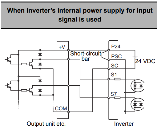
Sinking (NPN) Logic for Internal Power Supply
Ensure that the short-circuit bar is connected between P24 and PSC terminals. Connect the positive voltage input of the output unit to P24. Connect the COM of the output unit to SC.
Connect each signal output from the output unit to S1 through S7, depending on your required inputs.
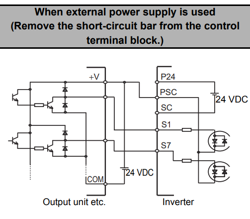
Sinking (NPN) Logic for External Power Supply
Remove the short-circuit bar. Connect the positive voltage input of the output unit to PSC, and the positive voltage terminal of the power supply. Connect the COM of the output unit to the negative or neutral voltage terminal of the power supply.
Connect each signal output from the output unit to S1 through S7, depending on your required inputs.
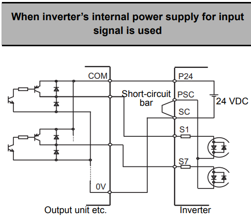
Sourcing (PNP) Logic for Internal Power Supply
Ensure that the short-circuit bar is connected between PSC and SC terminals. Connect the neutral (0V) voltage input of the output unit to SC. Connect the COM of the output unit to P24.
Connect each signal output from the output unit to S1 through S7, depending on your required inputs.
Sourcing (PNP) Logic for External Power Supply
Remove the short-circuit bar. Connect the neutral (0V) voltage input of the output unit to PSC, and the neutral voltage terminal of the power supply. Connect the COM of the output unit to the positive voltage terminal of the power supply.
Connect each signal output from the output unit to S1 through S7, depending on your required inputs.

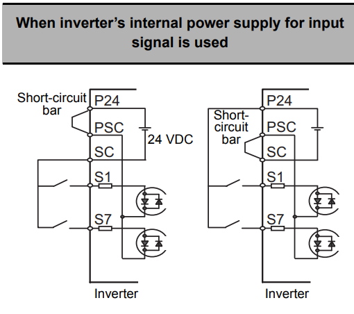
No-Voltage Switch for Internal Power Supply
Ensure that the short-circuit bar is connected between P24 and PSC terminals, or between PSC and SC terminals.
Connect SC or P24 to S1 through S7 with intermediary switches, depending on your required inputs.
Refer to the below image for the exact configurations.
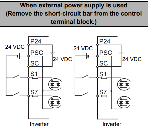
No-Voltage Switch for External Power Supply
Remove the short-circuit bar. Connect either the positive or negative terminal of the power supply to PSC.
Connect the remaining terminal of the power supply to S1 through S7 with intermediary switches, depending on your required inputs.
Refer to the below image for the exact configurations.
Output Wiring Configurations
Sinking (NPN) Logic
Connect the positive terminal of the external power supply to the input device's common terminal, connect the neutral terminal of the external power supply to PC.
Connect P1 and P2 to the input terminals of the input device as required.

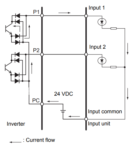
Sourcing (PNP) Logic
Connect the neutral terminal of the external power supply to the input device's common terminal, connect the positive terminal of the external power supply to PC.
Connect P1 and P2 to the input terminals of the input device as required.