Scenario
You would like to add a NX-EIC202 Coupler to your Network with a CJ Series PLC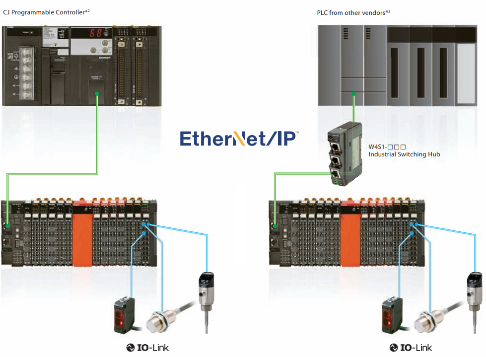
Solution
When it comes to setting up the NX-EIC202 Coupler, there are 3 parts to the setup process:
Part 1 - Unit IP Address Setup
There are several ways to set the IP address of the Slave Terminal. Specify the IP address setting method as follows with the rotary switches. Below we describe two common methods, but for more option please refer to the resource material: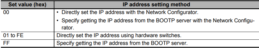
Method 1 - Set via Hardware:
- The two rotary switches show a two-digit hexadecimal number. The setting range is 0x00 to 0xFF with the default setting 0x00.
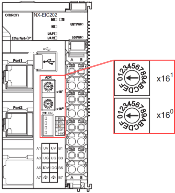
- Use the DIP switch pin 4 and rotary switches to directly set the IP address.
-
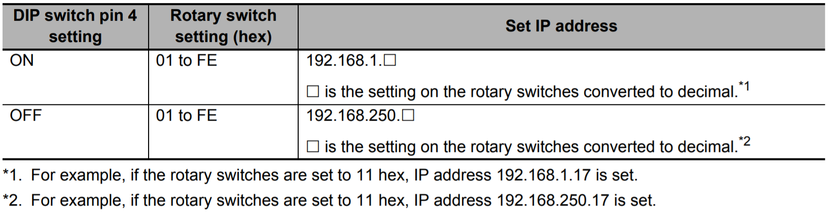
The following table shows the relationship between the switch settings and the set IP address:
Method 2 - Set via Network Configurator:
- Set both rotary switches to 0x0 and power on the EtherNet/IP Coupler Unit. The EtherNet/IP Unit will have the default IP address 192.168.250.1 (DIP switch 4 is OFF) or 192.168.1.1 (DIP switch 4 is ON). Make sure PC is set to static IP range of 192.168.x.x depending on DIP switch setting.
-
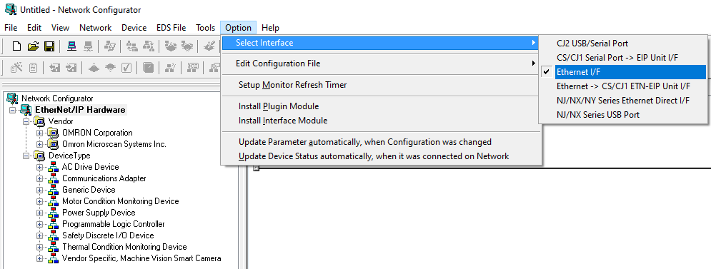
Open Network Configurator and Under Option - Select >> Interface. Then Select >> Ethernet/IF.
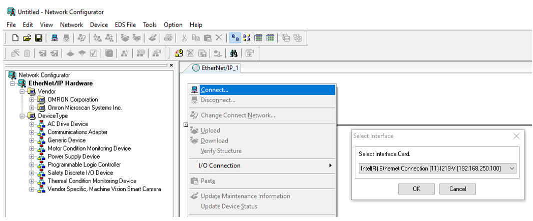
- Next Connect the Network Configurator online by Right clicking and selecting Connect.
-
Now select your network adapter that the coupler is connected to. Browse the network by clicking OK.
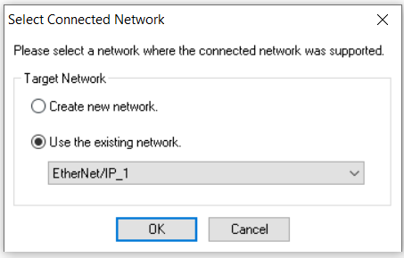
- Once the browsing is complete you can create a new network or use existing network and click OK.
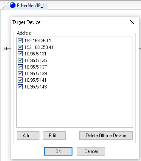
- Right click in the network and select upload, to upload connected device to the network. You will see a list of target devices. Click OK to upload EtherNet/IP devices to the network.
- Depending on DIP switch setting. The coupler will either be on 192.168.250.1 or 192.168.1.1.
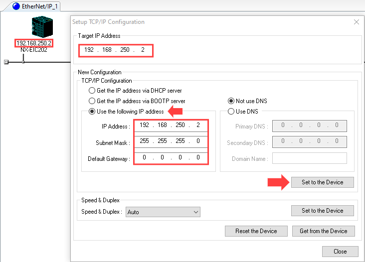
- Select Tools - Setup TCP/IP Configuration to display the following Setup TCP/IP Configuration Dialog Box, and set the TCP/IP Configuration for the target device. In the following example, the settings are all at their default values.
- Enter the IP address to set and press the Get from the Device button. The present setting will be obtained. Change the IP address in the New Configuration Box if required.
-
Press the Set to the Device button. The IP address will be transferred to the device. The applicable device is the device specified in the Target IP Address Box.
-
The device must be reset to enable the transferred setting. Power the EtherNet/IP Coupler Unit OFF and back ON or click Reset the Device button.
System Configuration Example: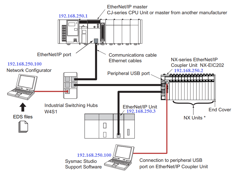
Part 2 - Setup the Unit I/O with Sysmac Studio
NX-IO Configurator software:
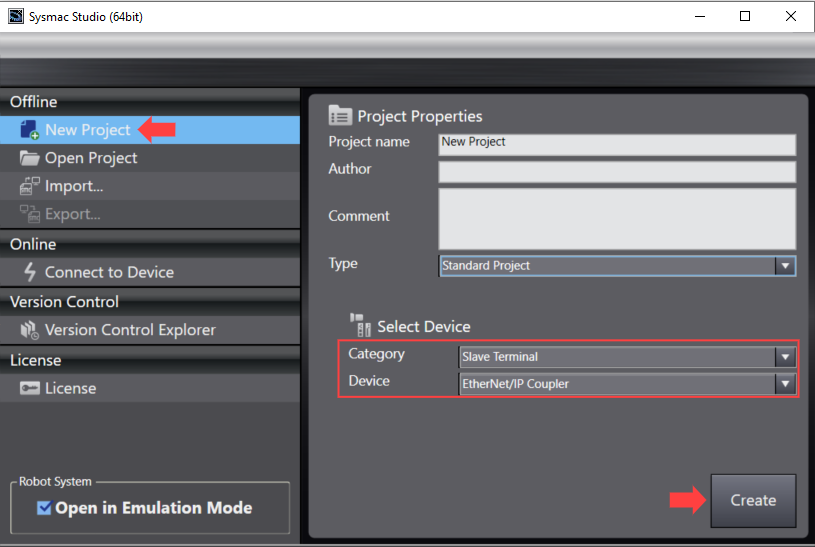
Getting started with Sysmac - First create your Sysmac project for the Slave device:
- Connect the EtherNet/IP Coupler Unit to a computer in which the Support Software is installed through a USB cable.
- Create a new project with the following settings. Category: Slave terminal Device: EtherNet/IP coupler.
There are 3 Methods to Configuring your Ethernet/IP Coupler unit
Method 1 - Auto Configure with Coupler Default Values
- When the coupler is first taken out of the box the coupler holds no memory.
- When the coupler is in this state you can auto configure the NX-IO units connected to the coupler on first start up.
- The coupler will perform an Auto scan of all the cards connected to the NX-Bus on power up.
Method 2 (Online) - Comparing and Merging with Actual Unit Configuration while connected online:
-
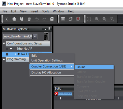
Right-click the EtherNet/IP Coupler Unit in the Edit EtherNet/IP Slave Terminal Configuration Tab Page >> Select Coupler Connection (USB) >> Online.

- Click the OK button. The Sysmac Studio goes online with the EtherNet/IP Slave Terminal.
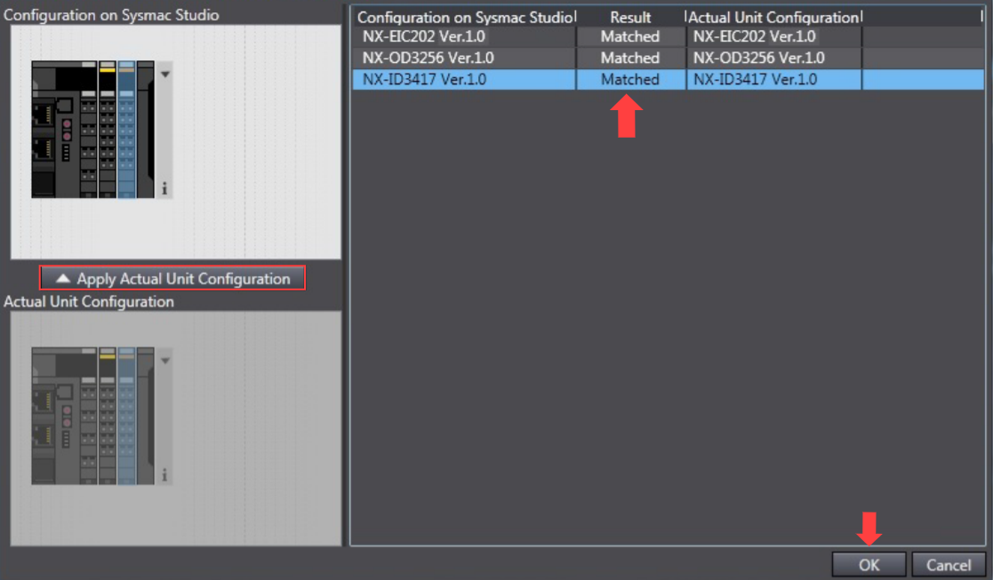
- Go online >> right-click anywhere in the Edit Slave Terminal Configuration Tab Page >> Select Compare and Merge with Actual Unit Configuration.
- To merge with actual Unit configuration, Click the Apply Actual Unit Configuration button. The configuration information on the Support Software will now match the actual Unit configuration.
- Click the OK button. The display returns to the Edit Slave Terminal Configuration Tab Page.
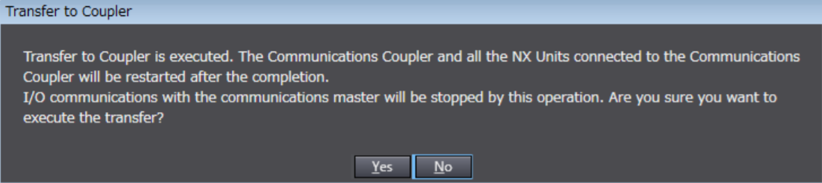
- Right-click the EtherNet/IP Coupler Unit in the Edit Slave Terminal Configuration Tab Page, and select Coupler Connection (USB) >> Transfer to Coupler.
- Select the data to transfer.
- To transfer the configuration information, Unit operation settings, and Unit application data, select Configuration Information + Unit Operation Settings + Unit Application Data.
- To transfer only the configuration information, select Configuration information only
-
Click the Yes button
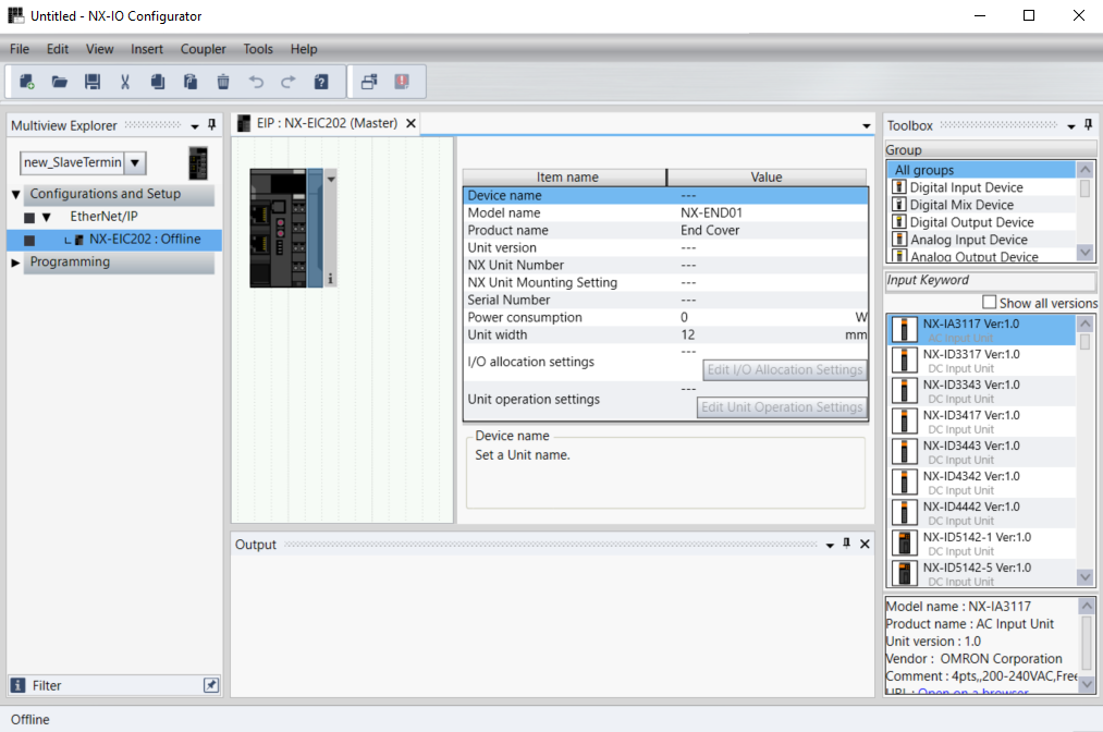
Method 3 (Offline) - Add the Inputs and Output Cards in the Project Manually:
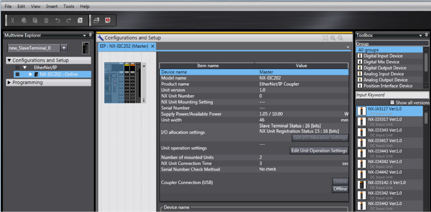
- Expand Configuration and Setup >> Expand EtherNet/IP >> Right Click on the NX - EIC202 Coupler.
- In the Toolbox on the right hand side select the group to which your cards belong in.
- Below the toolbox window is a list of available cards from the the selected card group.
- Double click or drag and drop the the cards that matches the hardware.
Now that the coupler topology matches the Hardware and Software side.
- Go Online with the coupler and transfer the settings to the coupler.
-
Right-click the EtherNet/IP Coupler Unit in the Edit EtherNet/IP Slave Terminal Configuration Tab Page >> Select Coupler Connection (USB) >> Online.
- Then Right-click the EtherNet/IP Coupler Unit in the Edit Slave Terminal Configuration Tab Page, and select Coupler Connection (USB) >> Transfer to Coupler.
- Select the data to transfer.
- To transfer the configuration information, Unit operation settings, and Unit application data, select Configuration Information + Unit Operation Settings + Unit Application Data.
- To transfer only the configuration information, select Configuration information only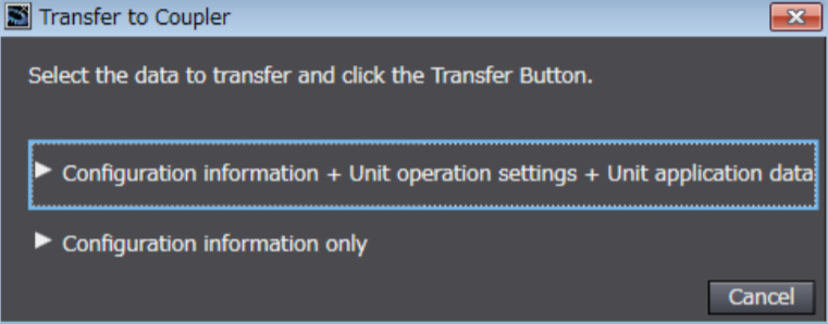
-
Click the Yes button

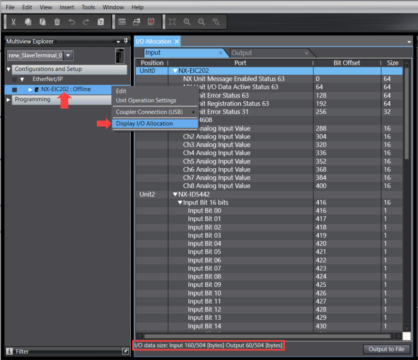
Use the following steps to view the input and output tag sizes that are configured in the EtherNet/IP Coupler Unit:
- In the Multiview Explorer >> Right-click the EtherNet/IP Coupler >> Select Display I/O Allocation from the menu.
- The I/O allocation indicates the input and output tag sizes (bytes) for the present configuration.
Part 3 - Define and Map the Ethernet/IP I/O Tags
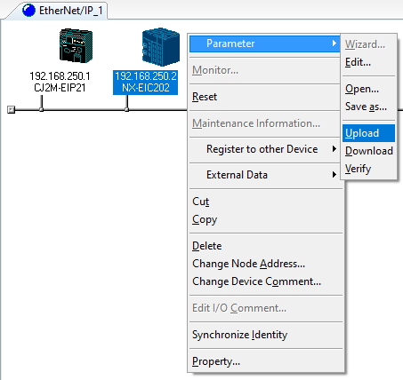
Use the Network Configurator to Upload the Slave Terminal Parameter:
- Use the following steps to view the input and output tag sizes that are configured in the EtherNet/IP Coupler Unit.
- Connect the Network Configurator to the network.
- Right-click the EtherNet/IP network and click Upload.
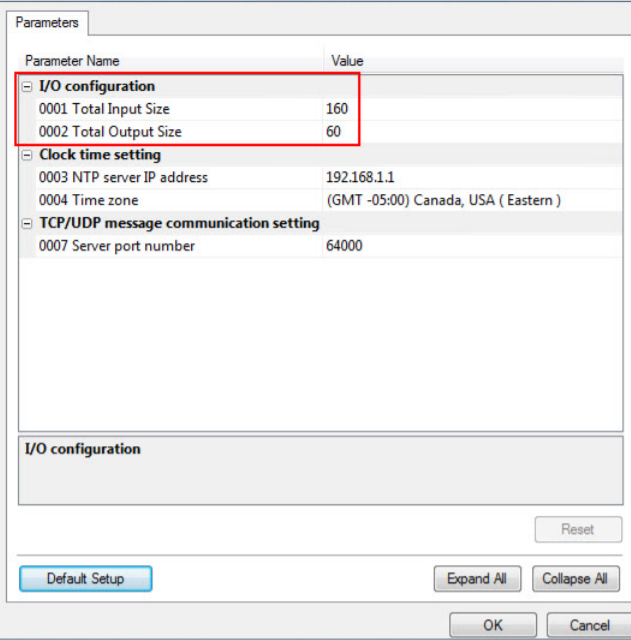
- Confirm the upload success and check the updated sizes. Right-click the EtherNet/IP Coupler Unit, select Parameter - Edit. The Edit Device Parameters Dialog Box should appear and indicate the Input and Output sizes.
- Double Click on the CJ2M CPU Icon.
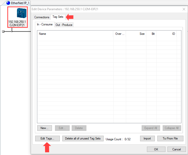
- Click the Tag Sets Tab at the top of the Edit Device Parameters Dialog Box.
There are two kinds of tag sets: input (consume) and output (produce). - Click on Edit Tags to create new Input and Output tag sets.
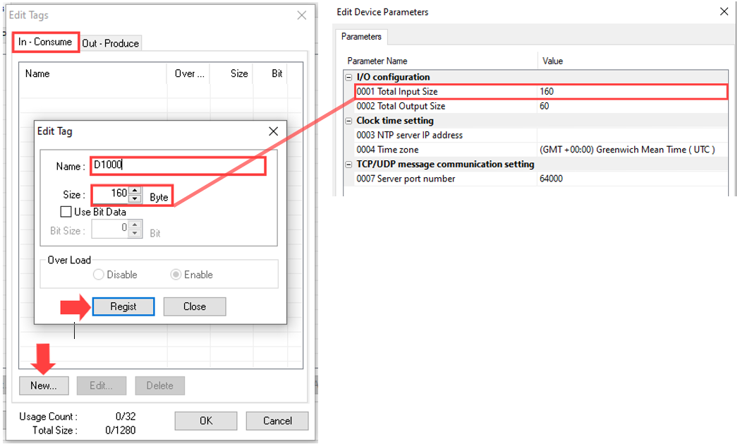
- Select between the IN tab and click on new to add a new tag set of specific area and Byte Size.
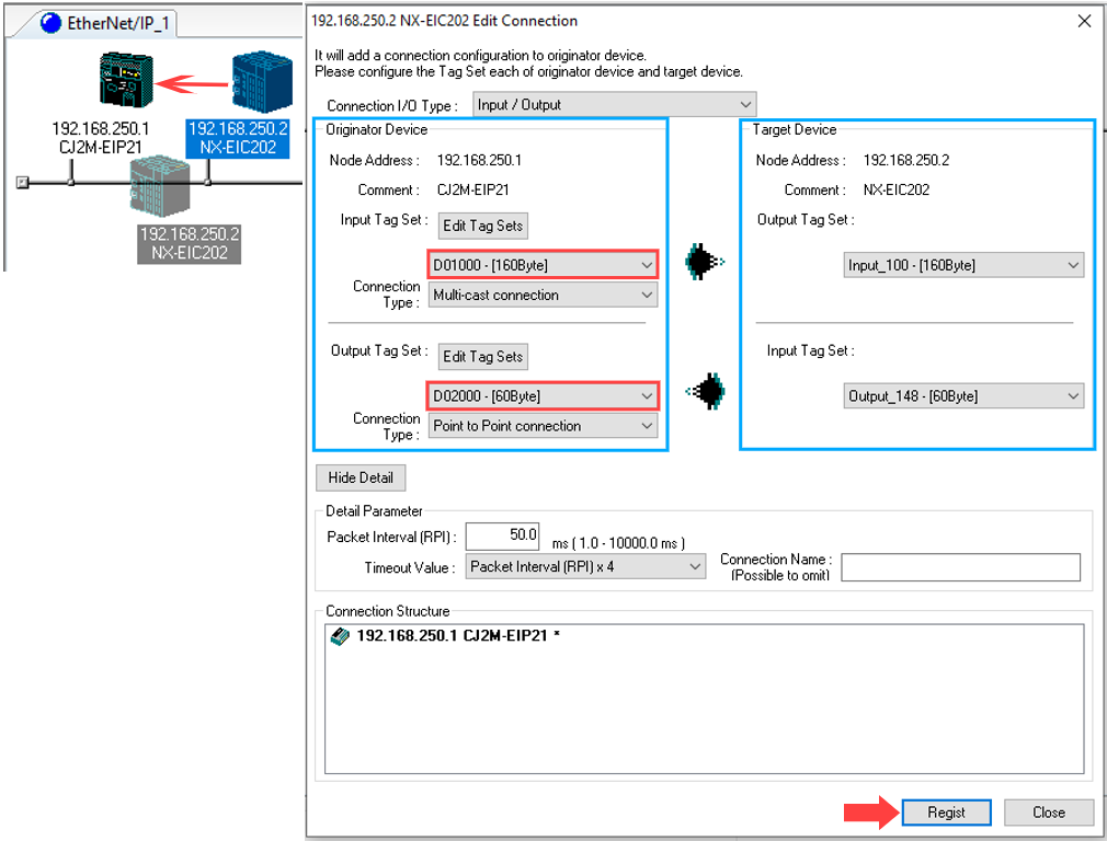
- Below Input tag set is defined first at the D1000 Memory area in the CJ2M CPU. The 160 Byte size matches the uploaded Total Input size.
- Create by clicking the Regist button. >> Click Close.
- Select between the OUT tab and click on new to add a new tag set of specific area and Byte Size.
- Below Output tag set is defined at the D1161 (160 Byte Offset) Memory area in the CJ2M CPU. The 60 Byte size matches the uploaded Total Output size.
- Create by clicking the Regist button >> Click Close.
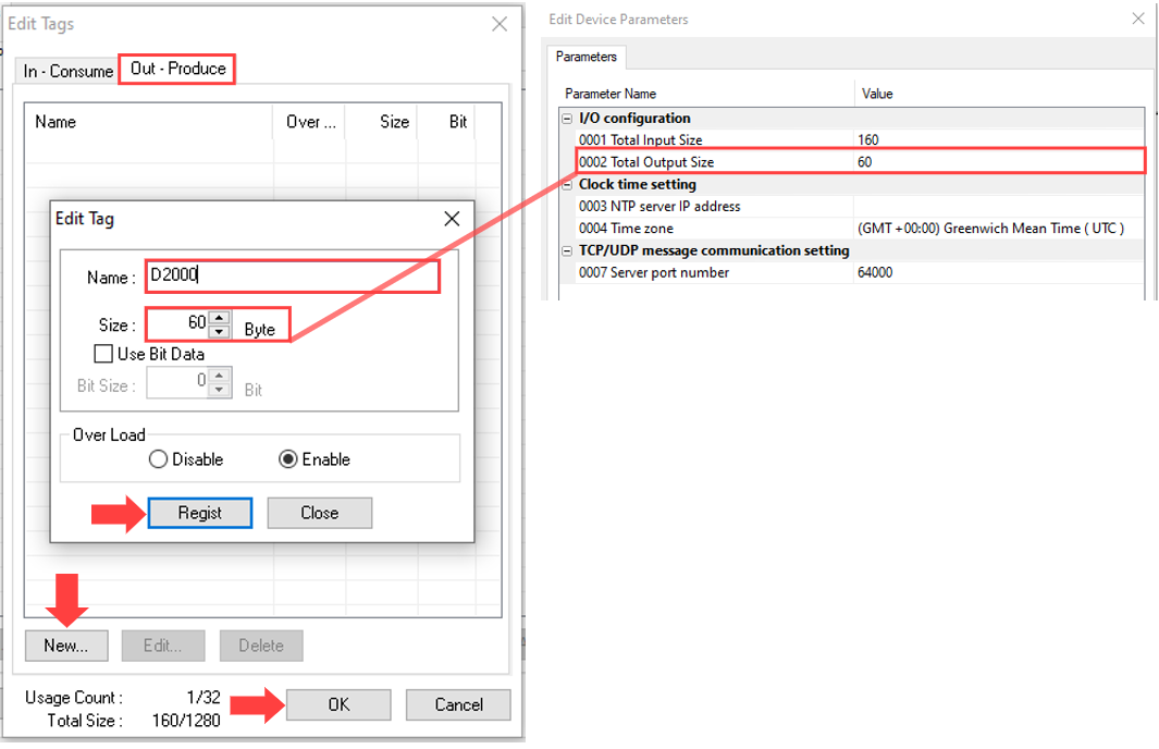
- Click OK >> Click Yes >> Click OK.
- Now that the IN/OUT tag sets are created we need to create a connection and map the tag sets between the CJ2M and the NX-EIC202.
- Click and hold down on the NX-EIC202 icon and drag and drop it on the CJ2M icon to create connection:
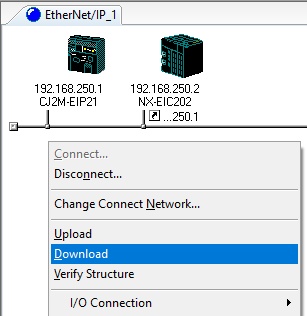
- Next step is to download the parameters to the network.
- Right Click in the empty space >> Download.
- If the Download after changed to Program mode button is clicked, all CPU Units are changed to PROGRAM mode and the parameters are downloaded. Confirm safety for all controlled equipment before you change the CPU Units to PROGRAM mode. You can restore the operating modes after the parameters are downloaded.
- You can click the Download with Current mode button to download the parameters even when one or more CPU Units is in RUN mode. The Download with Current mode button is disabled if the EtherNet/IP Unit does not support this function (e.g., revision 1 of CJ1W-EIP21).
- If the operating mode of one or more CPU Units was changed to download the parameters, you can return the CPU Units to the previous operating modes. If the No button is clicked, the CPU Units remain in PROGRAM mode.
Now that you have downloaded the Network configuration, you can find the reference addresses of you tags in CX - Programmer as follow:
- In D1000 - D1159 area - Input tags (160 Bytes)
- In D2000 - D2059 area - Output tags (60 Bytes)