How to Protect Transistor Outputs from Inductive Loads
A common cause of failure in digital outputs is the back EMF generated by inductive loads. Solenoids, fans, relays/contactors are all potential sources of large inductive loads. Without protection it is quite possible that the transistor powering the output can be irreversibly damaged by a large back EMF voltage spike.
The back EMF is generated when your output is switched off and the supplying current stops and magnetic field collapses. When the output magnetic field collapses the inductive load will generate its own field with the opposite polarity of the output. This induced voltage will potentially be at much higher voltages than the original output.
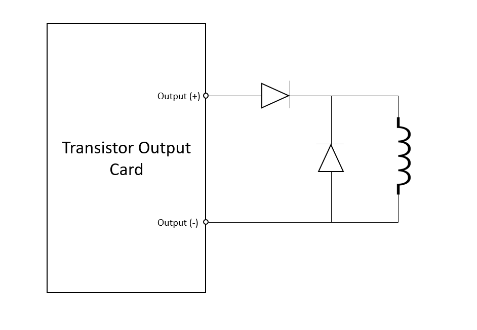
To prevent damage from this kind of load, we would suggest adding two diodes to your circuit. Connect one diode between your output and the load. This will stop the high voltage from reaching the output. Secondly, add a diode between the load positive and load negative - this is called a freewheel diode. This will give the back EMF a path to discharge safety.
Ensure that the diodes are rated for the inductance and energy dissipation. The peak reverse voltage ratings should be at least 2x the output rating. The forward current ratings should be at least 1.5x the output rating.