What is a Route Path?
In CIP communication, the PLC is instructed on how to transmit the message from its CPU through the network and to the destination device's CPU using a route path. The route path consists of three primary components: the path for leaving the client PLC, the IP address of the target PLC, and the path for reaching the target PLC's CPU.
Determining the route path for a simple system
In a straightforward setup, such as when a NX102 client communicates with a NX102 server, the route path can be quite simple. To ensure that the message is transmitted via the Ethernet port, the first component of the route path should be set to 02. The second component is the IP address of the server, let's say it is 192.168.250.2. Therefore, the complete route path becomes 02\192.168.250.2. On Omron PLCs, when communicating with the primary network port of the server PLC, the third component of the route path is not necessary. Hence, the final path would be 02\192.168.250.2.
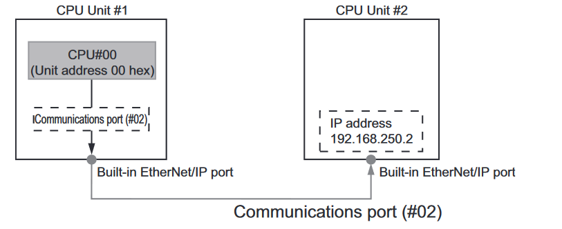
Network type number: "02" (Output the command via the built-in EtherNet/IP port)
• Destination address: Specify the destination IP address
• Route path: 02\192.168.250.2
Determining the route path for a complex system
In more intricate systems, EtherNet/IP adapters such as the CJ1W-EIP21 may be incorporated alongside an NJ CPU. In such cases, it becomes necessary to update the path to guide the client on how to route the data to the server CPU. The message must traverse through the backplane, the appropriate EtherNet/IP card, and the right device on the network before proceeding to the backplane and eventually to the server CPU.
When selecting the appropriate EtherNet/IP card, it's essential to note that the route path entry will use the Unit number + 10hex to identify the correct device. For instance, in the example provided earlier, the route path entry for EtherNet/IP Unit 1 was "#11" (Unit number: 1+10 hex).
Here's an example of how it would appear:
CPU Unit 1 to EtherNet/IP Unit 1:
- Network type number: "01" (Output the command via the internal backplane port)
- Destination address: "#11" (Unit address of EtherNet/IP Unit (Unit number: 1+10 hex))
From EtherNet/IP Unit 1 to EtherNet/IP Unit 2:
- Network type number: "02" (Output the command via the EtherNet/IP port)
- Destination address: Specify the destination IP address
From EtherNet/IP Unit 2 to CPU Unit 2:
- Network type number: "01" (Output the command via the internal backplane port)
- Destination address: "#00" (Unit address of the CPU Unit)
Delete