This article describes how you might connect a FHV camera to a CJ2 PLC via Ethernet/IP. The steps in this article are largely the same when dealing with the FH series camera or other Ethernet/IP compatible PLCs.
Configure the Camera
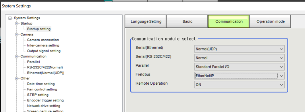
- Set the Communication Fieldbus to Ethernet/IP then Save and restart the Controller.
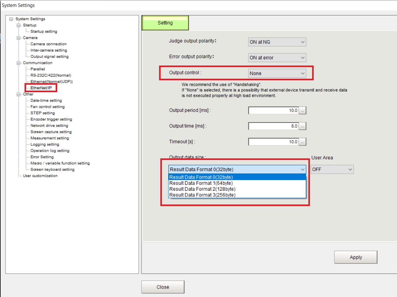
- In the Ethernet/IP menu, set the Output control to None and select the size of the Output Data. This SOP shows how to set up a 256 bytes Output data size.
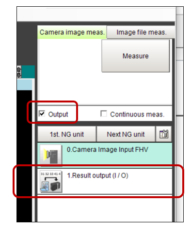
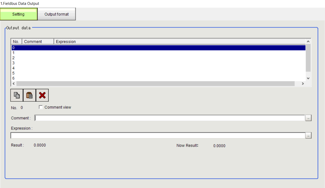
- Add a Result Output (I/O) (FH cameras will use Fieldbus Data Output instead) unit to the processing flow. Make sure the Output box is ticked so the Controller will output the results while in layout 0.
4. Set the outputs
Set the expressions for the fieldbus output according to the data you wish to send.
Open the Result Output (I/O) unit and select Fieldbus as the Output device.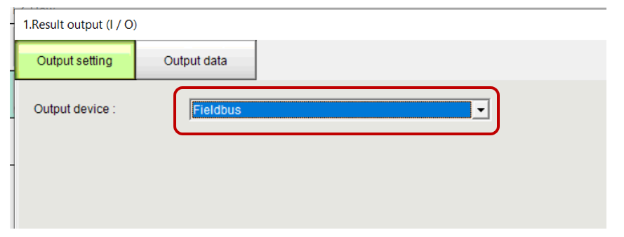
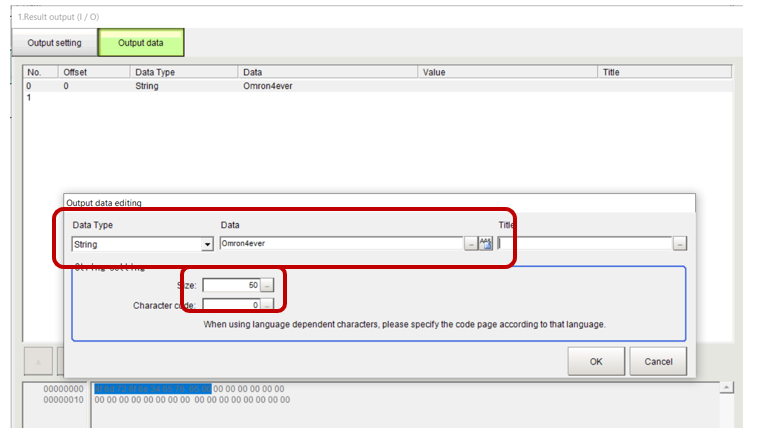
In the Output data tab, click Insert then set the data which you intend to send back to the PLC. Make sure the size is large enough to fit the data.
Configure the Ethernet/IP connection
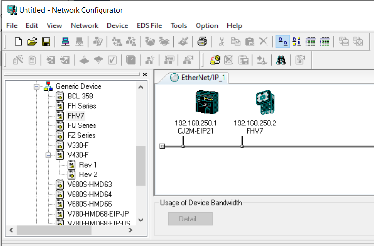
- Launch Network configurator
- Add the PLC and camera to the network. The EDS file for the FHV7/FH cameras should be included with network configurator.
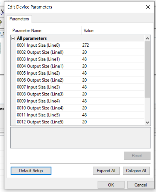
- Double click on the camera to configure the input/output sizes of the camera. In this example we chose Result Data Format 3 (256 bytes) and we are not using the user area. The earlier selection defines the size of the output area but does not include the status words. Use the below reference table when setting the input and output area.
| Output Area (Camera perspective) | User Area | Output Size |
|---|---|---|
| Result Data Format 0(32 bytes) | No | 48 bytes |
| Yes | 80 bytes | |
| Result Data Format 1(64 bytes) | No | 80 bytes |
| Yes | 112 bytes | |
| Result Data Format 2(128 bytes) | No | 114 bytes |
| Yes | 176 bytes | |
| Result Data Format 3(256 bytes) | No | 272 bytes |
| Yes | 304 bytes |
| Input Area (Camera perspective) | Input Size |
|---|---|
| Not using User Area | 20 bytes |
| Using User Area | 52 bytes |
In this example the input size would be 272 bytes and the output size would be 20 bytes.
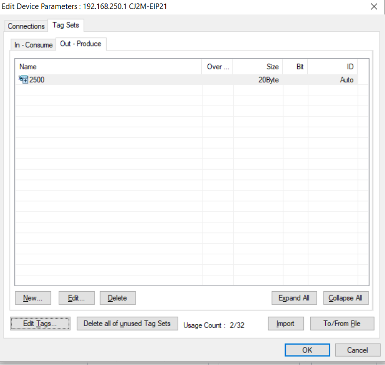
4. Configure matching tags on the PLC.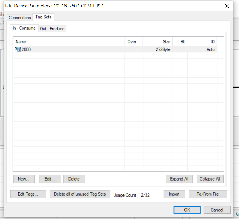
5. Create the connection.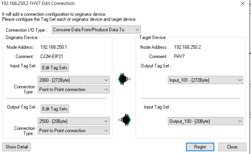
Create a PLC program
Information
Refer to the camera communications users manual for more information (Z342).
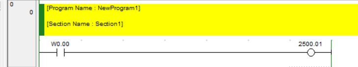
Trigger the PLC by setting the STEP signal
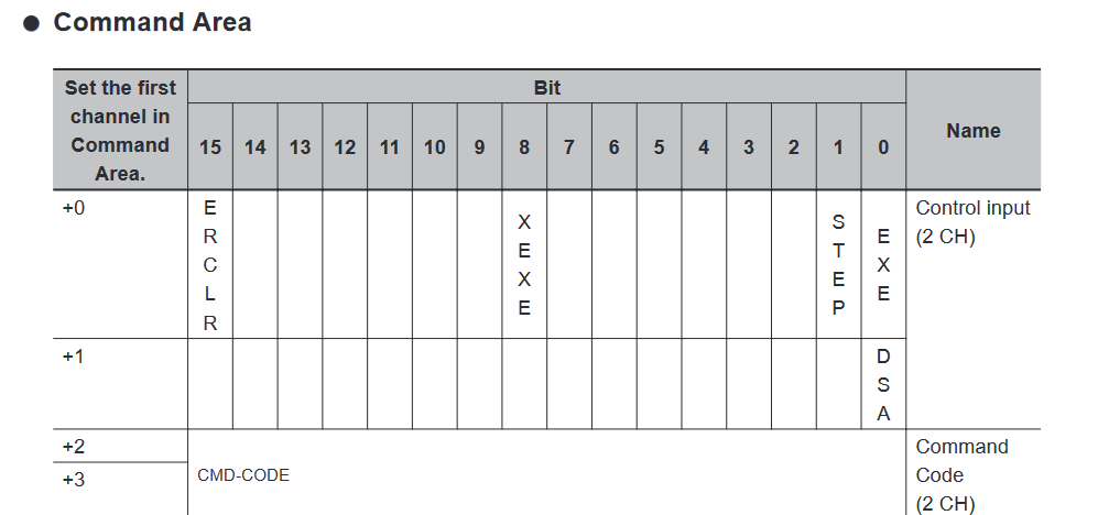
In this example the command word is at 2500, so the step signal is 2500.01
Read the overall judgement.
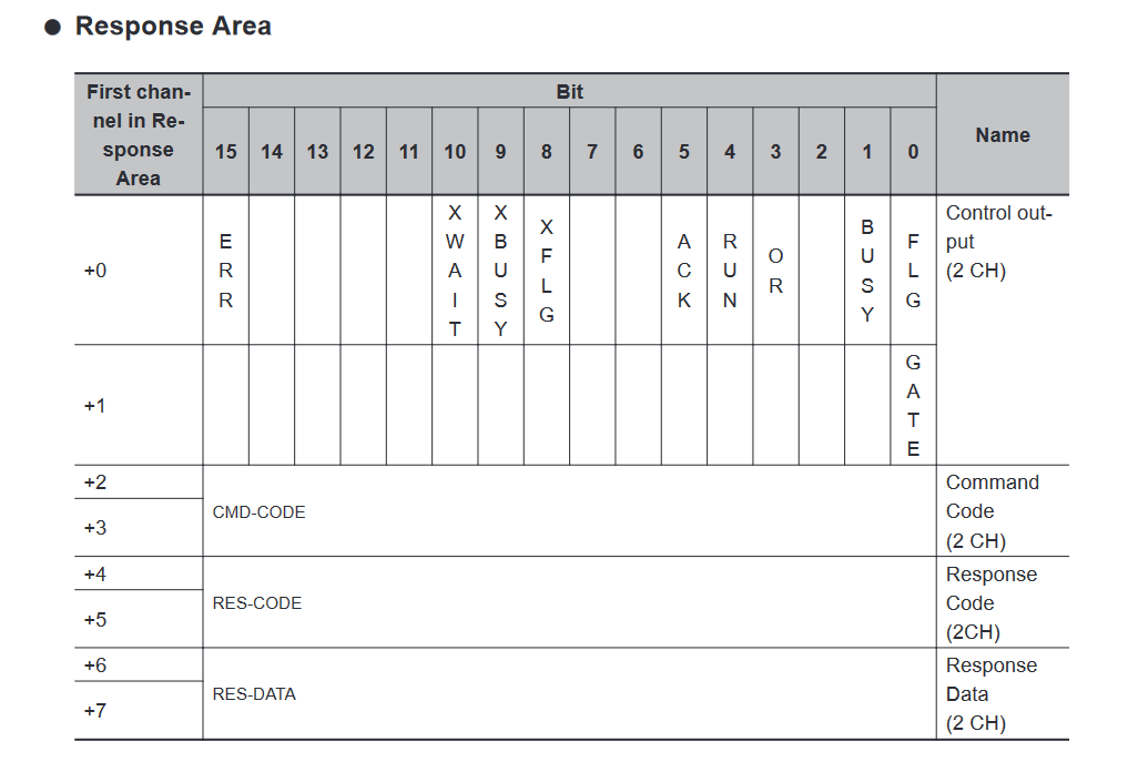
In this example the response starts at 2000 so the overall judgement is 2000.03.
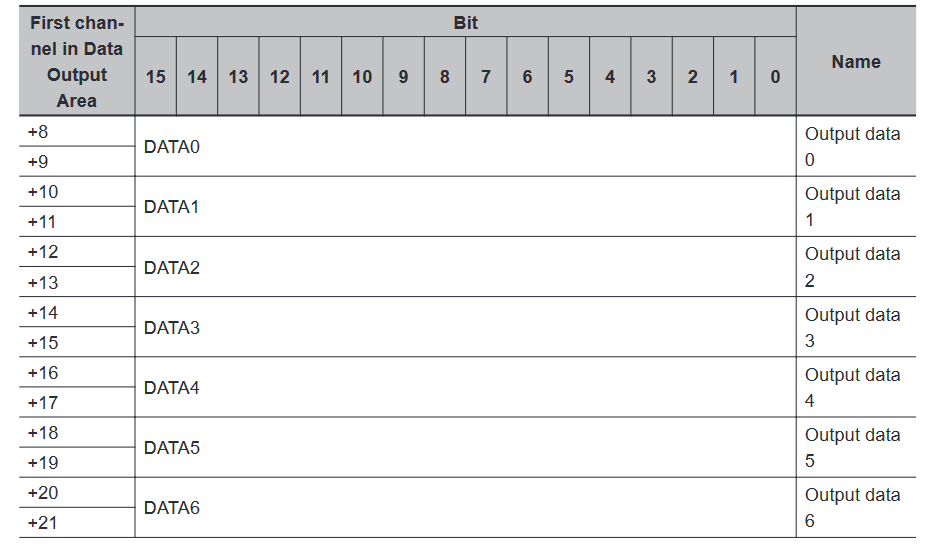
Read data from the PLC - the response data starts at offset +8, so the first output from Fieldbus Data Output or Result Output (I/O) is at 2008.