Introduction
The purpose of this article is to demonstrate the connection procedure between an NA5 HMI and a CS1G/H PLC, using a CS1W-ETN11 or CS1W-ETN21 ethernet unit.
Pre-Requisites
This article assumes prior basic knowledge of both Sysmac Studio and CX-Programmer, as well as basic knowledge of the physical setup of CS1G/H PLCs and NA5 HMIs.
Required Equipment
NA5 HMI
CS1G or CS1H PLC (Referred to as CS1G/H)
CS1W-ETN11 or CS1W-ETN21
Ethernet Switch and Ethernet Cable
Procedure
Physical Configuration
Step 1
If using a CS1W-ETN11, observe the eight rotary switches on the rear of the unit. These are used to set the IP address of the unit and should be configured before the unit is attached to the CS1G/H’s backplane.
Note that these switches are in hexadecimal, and can be individually set to values from 0 to F. The switches operate in pairs, as seen in the below image, to set the four octets of an IP address.
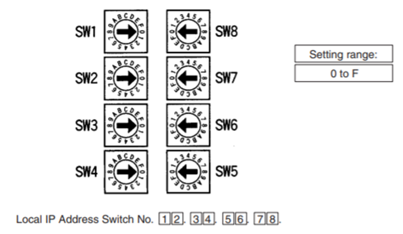
As an example, if an IP address of 192.168.250.1 is desired, the equivalent address in hexadecimal is C0.A8.FA.01, therefore the rotary switches would be set as shown in the below table.
SW1 |
C |
SW2 |
0 |
SW3 |
A |
SW4 |
8 |
SW5 |
F |
SW6 |
A |
SW7 |
0 |
SW8 |
1 |
Step 2
Install the CS1W-ETN11 or CS1W-ETN21 (referred to as the 'ethernet unit' from now) on the backplane used to power the CS1G/H PLC.
Step 3
Ensure that the Unit Number of the ethernet unit is unique. This number is set using a rotary switch on the front of the unit.
Step 4
Ensure that the FINs Node Address, which is set by two rotary switches on the front of the ethernet unit, is the same as the last octet of the IP address. Note that these switches are also in hexadecimal, therefore their values on the CS1W-ETN11 should match the values of SW7 and SW8 from above. For the CS1W-ETN21, the IP address is configured by software later in the process.
Step 5
Connect the ethernet unit and NA5 HMI to an ethernet hub using ethernet cable.
Configuring CS1G/H and CS1W-ETN11/21
Step 1
Connect the configuring computer to the CS1G/H through either the RS-232C serial port or the peripheral port.
Step 2
If connecting to the RS-232C serial port, refer to Appendix E of the Sysmac CS Series CS1G/H-CPU__H Programmable Controllers Operation Manual (W339-E1-20) for wiring details. Ensure that the DIP switches on the CS1G/H are set so that pin 5 is ON.
Step 3
If connecting to the peripheral port, connect a CS1W-CIF31 cable and a CS1W-CN226/626 cable, or refer to section 3.3.3 of the Sysmac CS Series CS1G/H-CPU__H Programmable Controllers Operation Manual (W339-E1-20) for details. Ensure that the DIP switches on the CS1G/H are set so that pin 4 is OFF.
Step 4
Create a Project in CX-Programmer. Ensure that the correct Device Type and CPU Type are selected. For Network Type, select either 'SYSMAC WAY' or 'Toolbus'.
Step 5
Ensure that the project can connect and 'Work Online' with the CS1G/H. Enter Program Mode.
Step 6
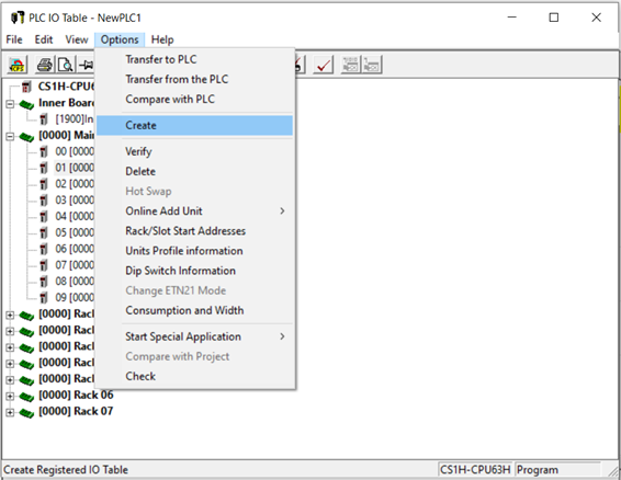
Double-click 'IO Table and Unit Setup' to open the PLC IO Table window. In this window, click on the Options menu and select Create, as shown in the below image. Click through any prompts that appear. This will detect and add the ethernet unit to the configuration of the CS1G/H.
Step 7
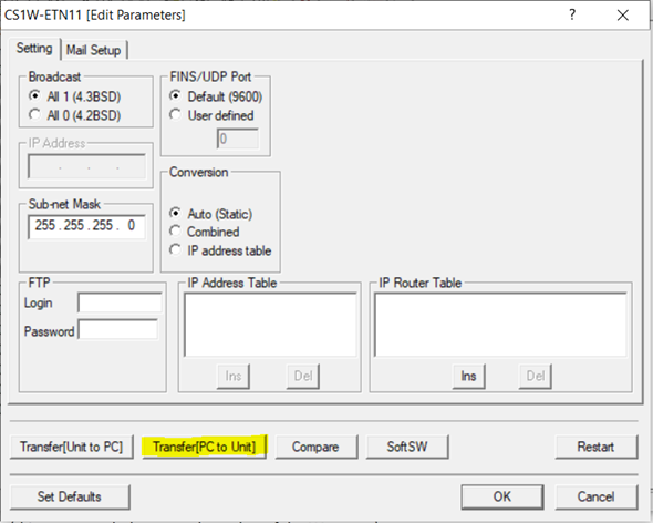
Check the PLC IO Table to ensure that the ethernet unit is present. It should appear on the Main Rack. Double-click on the ethernet unit to open the Edit Parameters window.
For a CS1W-ETN11, set the Subnet Mask as appropriate to the network. This procedure uses a Subnet Mask of 255.255.255.0.
For a CS1W-ETN21, set the IP Address and Subnet Mask as appropriate to the network. Ensure that the last octet of the IP Address is the same as the FINS Node Address (which was set using the rotary switches on the front of the ethernet unit).
Step 8
Transfer the settings to the device, as shown in the below image.
Step 9
In the main CX-Programmer window, go to the Tools menu and select Network Settings. This will open CX-Integrator.
Once opened, CX-Integrator may present a series of choices, depending on the exact configuration of the system.
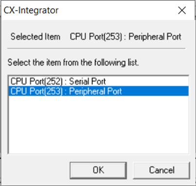
If asked about the port, as seen in the below image, select the port of the CS1G/H that the computer is connected to.
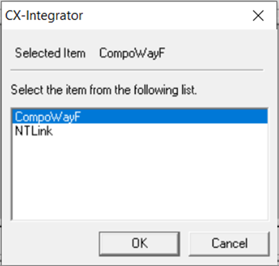
If asked to choose between CompoWayF or NTLink, as seen in the below image, select CompoWayF.
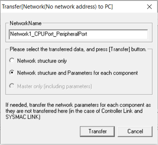
If asked about transferring network structure or network structure and parameters, as seen in the below image, select network structure and parameters. It is possible that the parameters will not be transferred completely, and an error or warning will appear. This error or warning can be ignored.
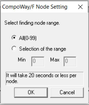
Lastly, if asked about the finding node range, as seen in the below image, select 'All'. CX-Integrator may warn about not being able to locate a Slave Node, this warning can be ignored.
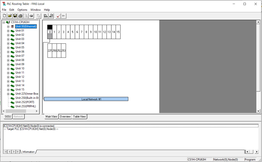
Step 10
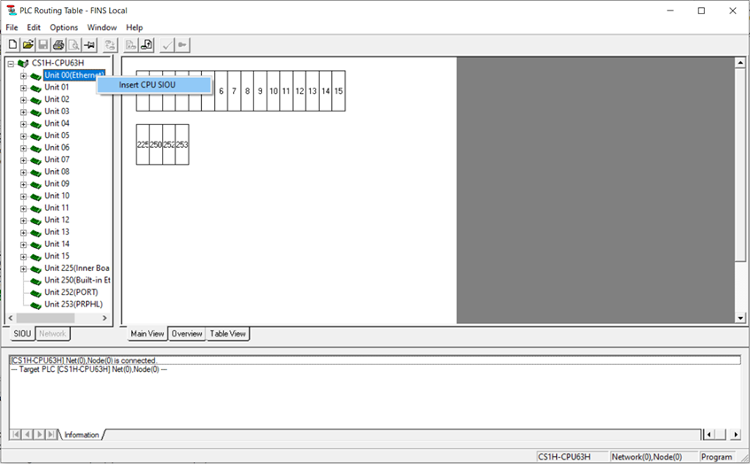
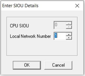
In the CX-Integrator's main window, go to the Tools menu and select 'Start Routing Table'. This will open the PLC Routing Table - FINS Local window. On the left side of this window, the units installed on the CS1G/H are listed. Locate the ethernet unit in this list. It should be presented with the Unit Number previously allocated to the unit. In the below image, the ethernet unit had been allocated the Unit Number of 0. Right-click on the ethernet unit and select the Insert CPU SIOU option.
This will cause CX-Integrator to request a Local Network Number. The default for connecting to an NA5 HMI is 1, as shown in the below image, but another number can be selected if required. 0 cannot be used.
Once this is complete, the configuration should appear similar to the below image.
 Use the buttons on the top of the PLC Routing Table - FINS Local window to transfer the configuration to the CS1G/H.
Once this transfer is complete, close CX-Integrator, and cycle the power on the CS1G/H.
Configuring the NA5 HMI
Step 1
In Sysmac Studio, crate a project and insert an NA5 HMI. Ensure that the communication setup for the HMI, which is located under the HMI menu, is set to the correct method for the connection between the programming computer and the HMI.
Step 2
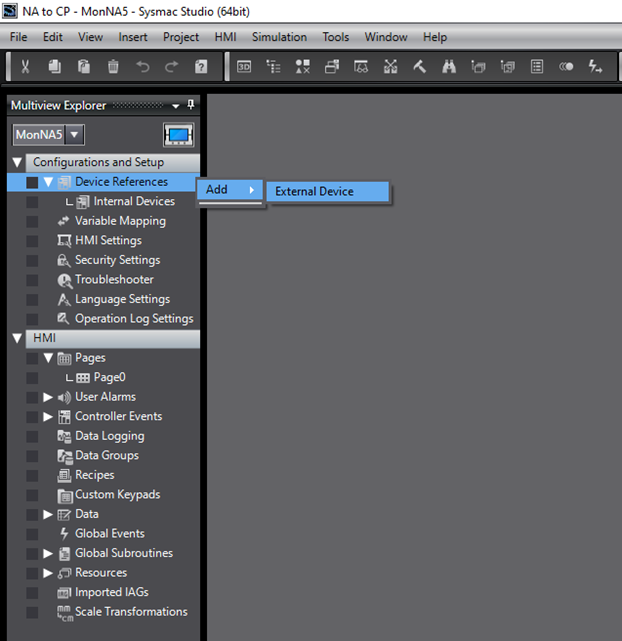
Add an external device by right-clicking on the device reference in the Multiview Explorer, then selecting Add, followed by External Device, as shown in the below image.
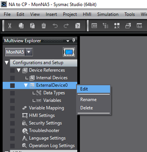
Once the external device has been added, double-click on the new external device to open the settings tab. Alternatively, right-click on the external device and select Edit, as shown below.
Step 3
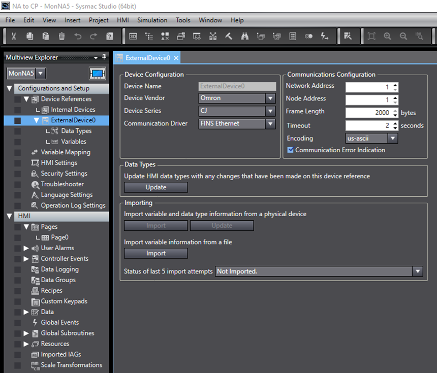
In the external device's Settings tab, locate the Device Configuration section in the top left. In this section, set Device Series to CJ, and Communication Driver to FINS Ethernet. Note that even though the connected device is a CS1G/H, the correct setting is CJ.
In the same tab, locate the Communications Configuration section in the top right. In this section, ensure that the Network Address matches the Network Address that was previously set in CX-Integrator (in this procedure, the Network Address was set to 1). Additionally, ensure that the Node Address matches the FINS node number that was set in the ethernet unit. This Node Address must be the same as the last octet of the IP Address.
The below image shows these settings, assuming that the IP Address of the ethernet unit was 192.168.250.1.
Step 4
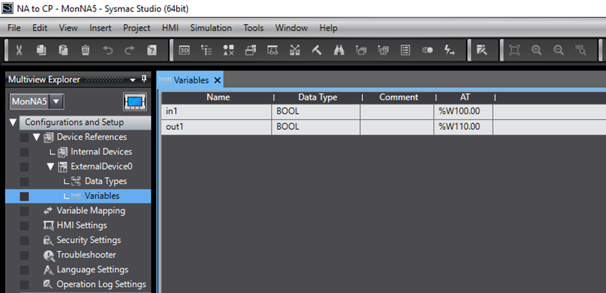
To set up the variables that will interact between the NA5 HMI and CS1G/H PLC, go to the Variables tab, located under the recently added External Device in the Multiview Explorer.
Enter the desired variables that will be used in communications between the CS1G/H and the NA5 in this tab. To properly configure these variables, any name may be used, but the addresses of the variables must be entered into the AT column, as shown in the below image. Note that these variable addresses must be preceded with a percentage symbol (%). Additionally, take care to ensure that the addresses are identical to those used on the CS1G/H.
Step 5
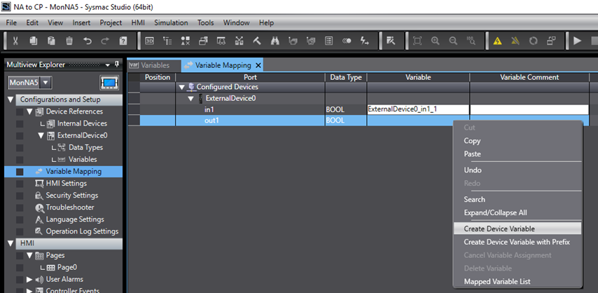
The variables need to be mapped to the NA5,to enable them to be referenced in the program. Navigate to the Variable Mapping tab in the Multiview Explorer. This tab will last the variables associated with the external device, as shown in the image below. A custom variable name can be entered in the Variable column, or variable names can be automatically generated by right-clicking on the variable and selecting Create Device Variable, as is also shown in the below image.
Step 6
Synchronise the program with the HMI. The configuration is now complete.
Testing
Once the above configuration is complete, the system can be tested by creating a momentary switch and a lamp on an HMI screen, and assigning them to mapped variables. These variables can then be monitored in the CX-Programmer watch window as they are changed using the HMI.