Scenario
You need to connect an Omron TM robot to a Omron NX/NJ PLC. This connection is setup using the TCP socket config, where the Cobot sends a string based message to the PLC and receives a response back.
Reference documents
https://assets.omron.eu/downloads/manual/en/v6/i624_tm12_and_tm14_series_installation_manual_en.pdf
Hardware Setup
Both the TM controller and NX/NJ PLC need to be connected through an ethernet port. On the TM controller this is located at the point labelled 'LAN'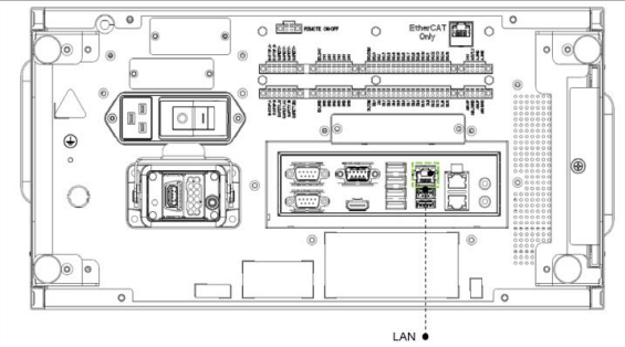
On the NX1P2 PLC, the ethernet cable is connected to port 1 Ethernet/IP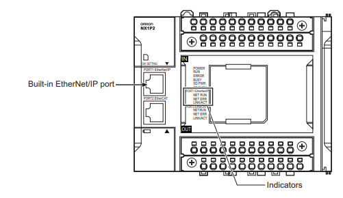
Solution
TM12 Setup
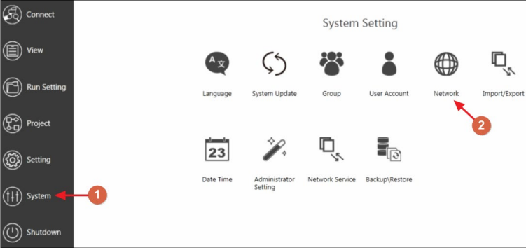
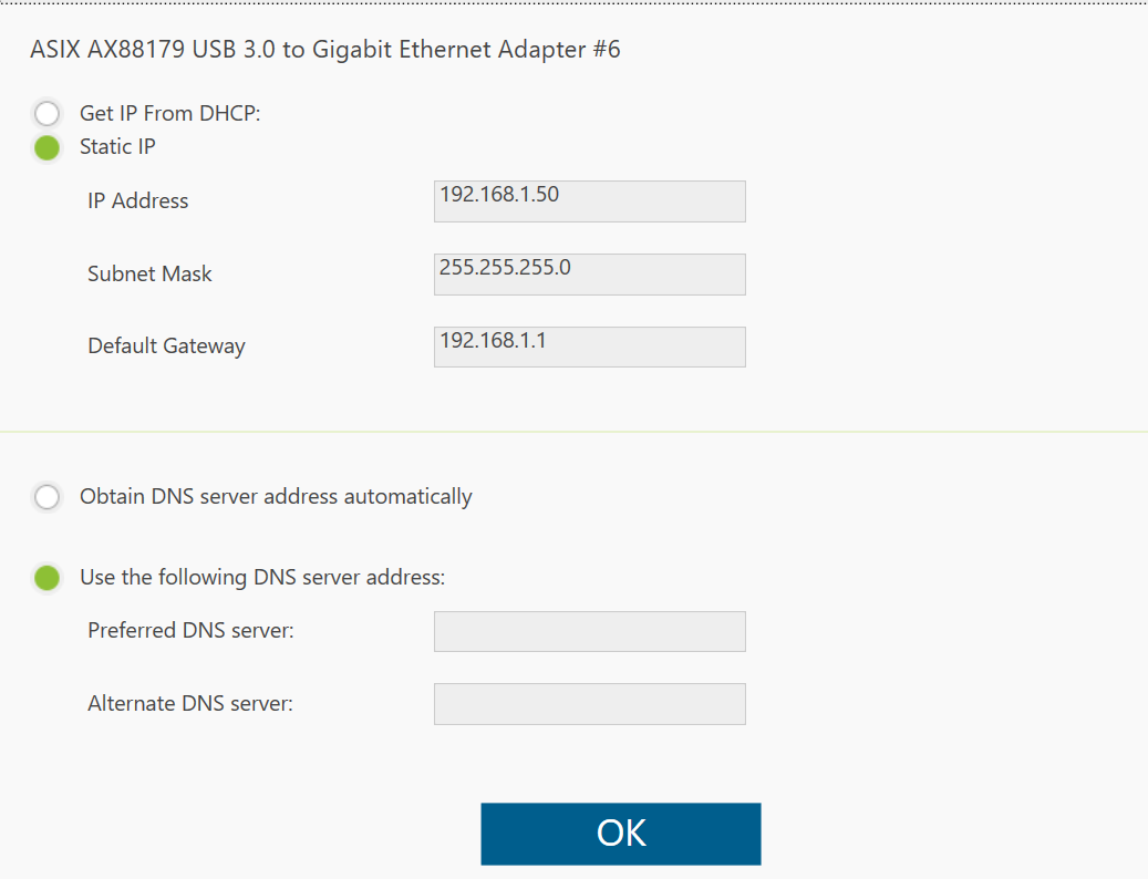
- The first step is to setup the IP addresses on the Cobot and PLC controller. In TM flow, go to system settings and select the network icon.
- Under Network settings, change the local area connection to static IP and IP address of the external network. It should be noted the Cobot and PLC must be on the same IP address and subnet to communicate, such if the cobot is on 192.168.250.50, then the PLC will need to have an address such as 192.168.250.10.
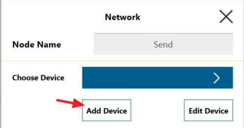
- Add a network node interface on TM flow and Add Device
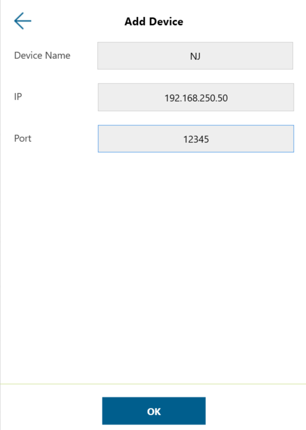
- Enter the device name, IP address and port number
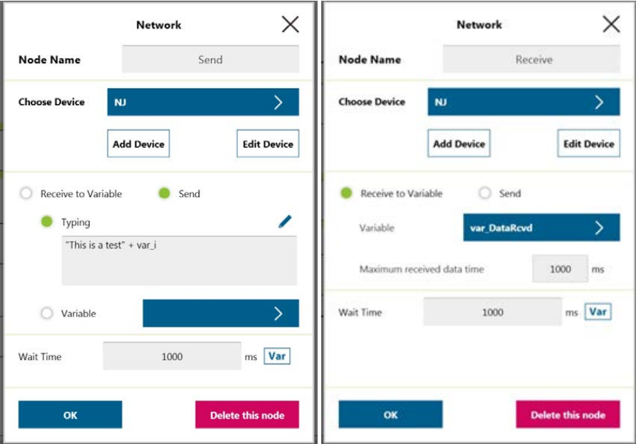
- On TM flow, add 2 network nodes, one for sending and one for receiving. In this example a SET node was also used to verify the communications is working correctly.
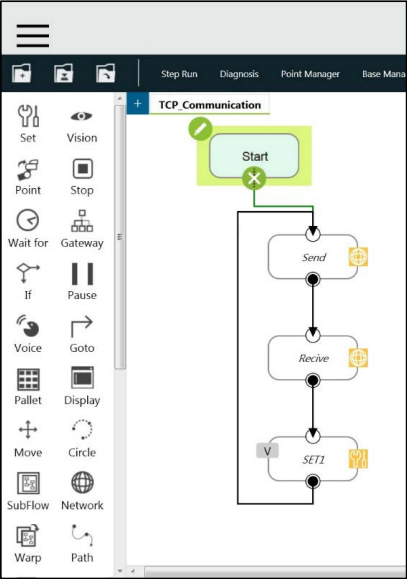
- To send or receive information, a data string or variable will be sent. The two network nodes will be required to be set up as either a send network or receive to variable.
-
 On completion of the program, press and hold the 'Play' button button for 2 seconds to execute the program.
NX PLC setup
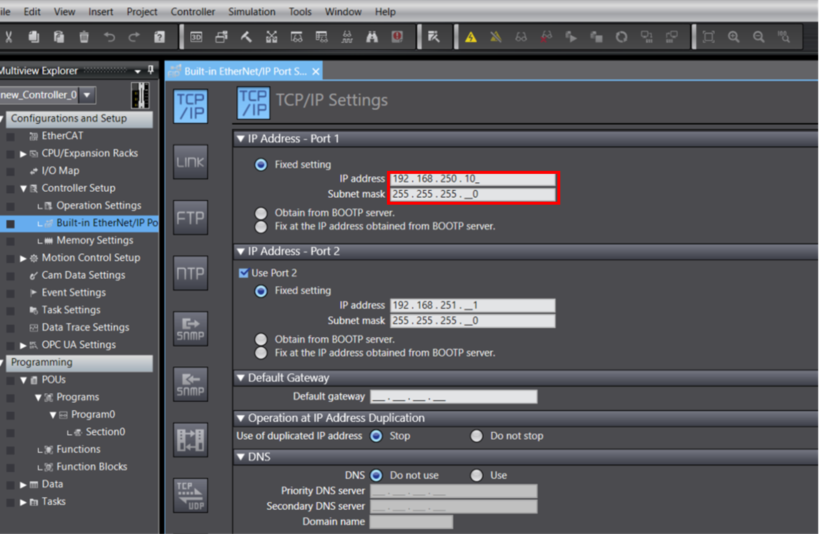
On the PLC connection side, the IP address needs to be set by opening Sysmac Studio. Navigate to Configurations and Setup> Built-in EtherNet/IP Port Settings>TCP/IP> IP. Ensure the PLC IP address in on the same subnet but a different IP address number such as 192.168.250. XXX
Creating the PLC program
To create the program, the TCP function blocks will be used, located under communications in the toolbox. 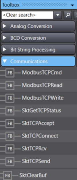
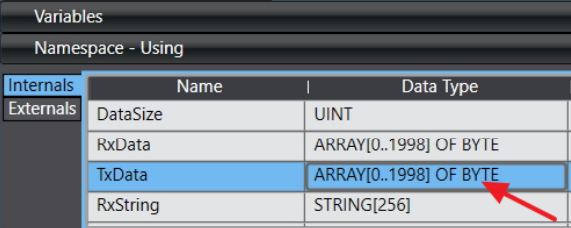
For the PLC and Cobot to communicate using TCP, the data that will be sent and received is a Byte array that will need to be converted to type ARRAY[0..1998] OF BYTE.
The ladder program involves using the TCP function blocks in the following order to successfully communicate using a TCP socket.
- To start the program, SktTCPStatus needs to be pulsed when the program is not running and the port is ready. this FB will accept the connection from clients.
- SktTCPAccept will check the ports current status and if any messages are available for receiving.
- The data needs to be processed and monitored using the DatRcvFlag, oand set to true on the SktGetTCPStatus FB.
- StkTCPSend is used to send data to the port
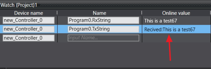
- build and upload program to PLC. Open the watch window on Sysmac and Display manager on TM flow to watch the communication occur.
The TCP Socket is successfully working if the watch window on Sysmac diplays a message like the example below.