Introduction
This guide is a step-by-step guide to walk you through connecting your CS or CJ ETN21 Ethernet Communication Unit to your PLC and enabling it to communicate over an ethernet network.
Pre-Requisites
Basic knowledge of CX-Programmer.
Basic knowledge of IP addresses and the construction of Ethernet Networks.
Please refer to these Precautions and Terms and Conditions which relate to the information and program samples provided before proceeding
Procedure
Pre-Setup
Determine the IP address and subnet mask for the ETN21 unit. The network number of the IP address, and the subnet mask, should be the same as other devices on your network, while the host number must be unique.
For example, the IP address of 192.168.250.1, with a subnet mask of 255.255.255.0, contains a network number of 192.168.250, and a host number of 1. If another device is connected to this network, it should use an IP address of 192.168.250.x, where x is any number other than 1, and a subnet mask of 255.255.255.0.
Physical Setup
Step 1 - Set the Unit Number
The unit number is set by manipulating the rotary switch labelled 'UNIT No.' on the front of the ETN21 unit. This switch can be set for a range between 0 and F.
Please use a small screwdriver to manipulate the rotary switch, and take care to avoid damage to the plastic.
The appearance of the rotary switches differs between the CS and CJ ETN21, as shown below.
CS ETN21
CJ ETN21

Step 2 - Set the Node Number
The node number is set in a similar manner to the unit number, by manipulating rotary switches on the front of the ETN21 unit. In this instance, there are two rotary switches labelled 'NODE No', one labelled as 'x161' and the other as 'x160'. These provide a range between 01 and FE in hexadecimal (or 1 to 254 in decimal).
Please use a small screwdriver to manipulate these rotary switches, and take care to avoid damage to the plastic.
The appearance of these rotary switches differs between the CS and CJ ETN21, as seen previously in Step 1.
The node number of an ETN21 unit should match the last octet of the units IP address. For example, if the IP address of an ETN unit is 192.168.250.1, then the node number should be '01'. For larger numbers, conversion from decimal to hexadecimal is required.
Step 3 - Mounting to a PLC
For a CS-series PLC, the CS ETN21 unit can be mounted to any of the existing slots on the backplane of the CPU rack, or an expansion rack. A maximum of four ethernet units can be mounted to a single PLC. Additionally, if other CPU Bus Units are installed, the maximum total number of CPU Bus Units is sixteen for a single PLC.
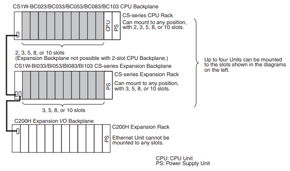
Note that the CS ETN21 consumes a maximum of 380mA. Ensure that the total current consumption of all the units connected to the same backplane or expansion rack does not exceed the output of the power supply.
For a CJ-series PLC, the CJ ETN21 unit can be mounted to either the CJ-series CPU rack, or an expansion CPU rack. Ensure that the sliders on the top and bottom of the ETN21 unit are used to lock the unit to the rack. A maximum of four ethernet units can be mounted to a single PLC. Additionally, if other CPU Bus Units are installed, the maximum total number of CPU Bus Units is sixteen for a single PLC.
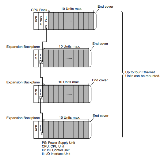
Note that the CJ ETN21 consumes a maximum of 370mA. Ensure that the total current consumption of all the units connected to the same CPU rack or expansion CPU rack does not exceed the output of the power supply.
Step 4 - Network Installation
Before installing ethernet system infrastructure, take care to follow ISO 8802-3 specifications. Do not install ethernet equipment near sources of noise, or if unavoidable, take adequate measures to control for noise interference, such as shielding or optical links.
Use a standard twisted-pair ethernet cable and ethernet hub. Connect the cable to the hub, making sure to press in the cable until it locks into place.
Connect the cable to the connection port on the ETN21 unit. Make sure to press in the cable until it locks into place.
The PLC should now be turned on.
PLC Configuration
There are several different methods to configure the PLC. This guide will concentrate on using CX-Programmer for this task. Please ensure that you have the latest version of CX-Programmer installed.
Step 1 - I/O Tables
I/O tables are used to identify the components mounted to the PLC, therefore whenever a change is made to the configuration of a CS or CJ-series PLC, it is necessary to create or update the I/O table and register the changes.
In CX-Programmer, connect to the PLC and ensure that you are working online. Transfer the program from the PLC using the buttons at the top of the window, or the keyboard shortcut CTRL+SHIFT+T.
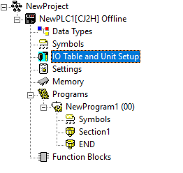
In the explorer view on the left side of the CX-Programmer window, double-click on 'IO Table and Unit Setup'.
This will open the PLC IO Table, which will look similar to the below image. Note that slight differences are likely, as this table contains the configuration information for your system. If no information is present, use the buttons at the top of the window to Transfer IO Table from PLC.
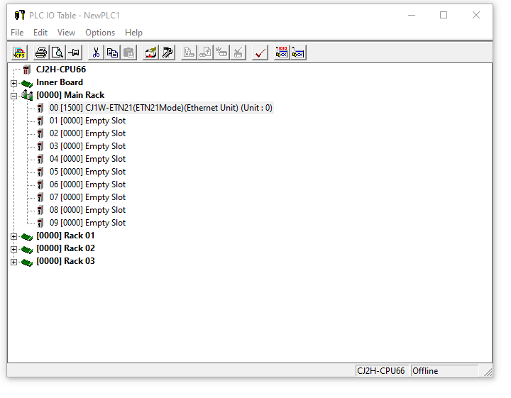
Ideally, the ETN21 unit will be included in the appropriate position on this table. If it is not, it can be added by double-clicking on the appropriate empty slot and selecting it from the presented list. Note that the ETN21 unit can be run in ETN11 or ETN21 mode. Normally, ETN21 is the correct choice, but ensure that you select the appropriate mode for your unit.
Right-click on the ETN21 unit in the PLC IO Table and select 'Unit Setup'. This will open the below window, with the default values.
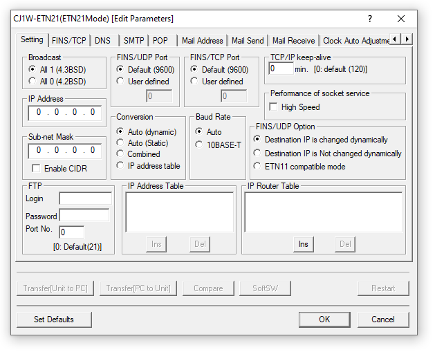
Make any required setting changes on this window. Normally, IP Address and Subnet Mask are the only required changes, but depending on your application, other changes may be required.
Click 'OK', then use the buttons at the top of the PLC IO Table window to Transfer IO Table to PLC. Once this transfer is complete, restart the PLC.
The ETN21 unit is now capable of communicating over a standard ethernet connection.
Step 2 - FINS Communication
When using the FINS communication service, routing tables must be established in advance. Routing tables are only required in the following circumstances,
- When communicating with a PLC or computer on another network.
- When multiple communications units are mounted to a single PLC.
- When routing tables are used for one or more other nodes on the same network.
Note that it is not necessary to use routing tables if one ETN21 is connected to the PLC, and the nodes are connected as a single network.
To establish the routing tables, navigate back to the PLC IO Table window from the previous step. Right-click on then ETN21 unit in the table, and select 'Start Special Application' then 'Start with Settings Inherited'. This will open CX-Integrator.
At the top of the CX-Integrator window, use the buttons to Work Online with the network. This may require you to stop working online in CX-Programmer.
Once working online in CX-Integrator, use the buttons at the top of the window to Transfer (Network to PC). This will load the current network configuration into CX-Integrator.
Select the 'Tools' menu, then 'Start Routing Table'. When prompted to select between FINS Local or FINS Network, if you are establishing a routing table for local devices, select FINS Local. This will open the following window.
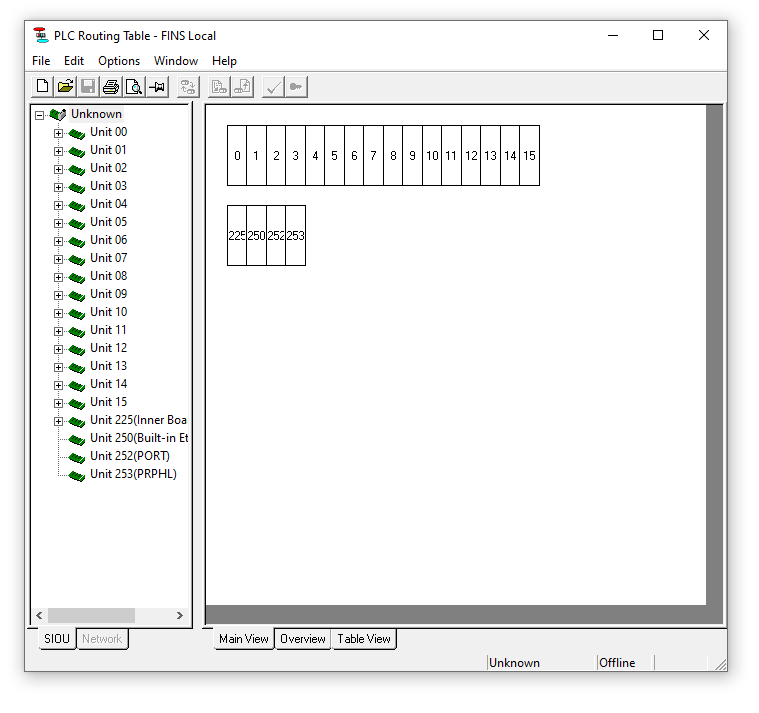
In this view, the network configuration of your system should be displayed on the left hand side. If it is not, use the buttons at the top of the window to Transfer from the PLC. Note that the unit numbers in this section correspond to the unit numbers of the components of your system in the PLC IO Table from CX-Programmer.
To establish the routing table for a unit, right-click on the unit number, select 'Insert CPU SIOU', and then choose an appropriate network number. This network number may depend on other devices in the network, for example if connecting to a Human-Machine Interface (HMI) such as an OMRON NS, NA or NB, you would need to match the network number for that device.
Alternatively, select the 'Table View' tab at the bottom of the screen. This brings up the following view.
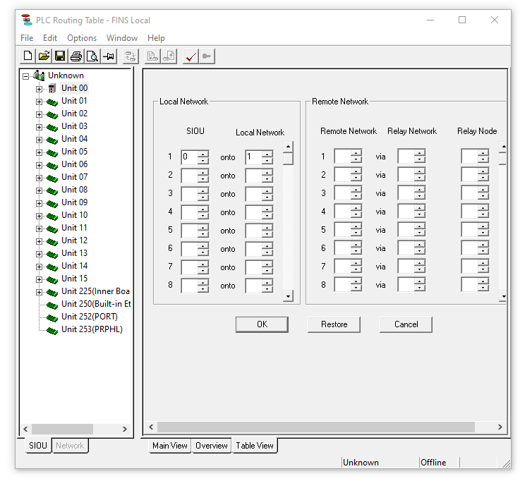
In this view, the network number can be assigned directly to the SIOU, which refers to the unit numbers on the left of the window. For example, in the above image, unit number zero has been connected to network number one.
Once the routing tables are established, use the buttons at the top of the window to Transfer to the PLC. Restart the PLC.
Step 3 - Communications Test
At this point, it should be possible to communicate with the ETN21 unit over ethernet. This can be tested by using a computer to send a PING command. This guide assumes the use of a Windows-based computer.
To perform this test, connect the computer to the ethernet hub connected to the ETN21 unit. Ensure that the PLC is on and the ETN21 unit is powered.
The computer should have an IP address with the same network number and subnet mask as the ETN21 unit. For example, if the ETN21 unit has the IP address 192.168.250.1, then a valid IP address for the computer could be 192.168.250.5.
Once connected to the ethernet hub, open the command prompt on the computer. This is done by pressing the Windows key and typing 'cmd' then pressing 'enter'. Type 'ping' into the window that appears, followed by the IP address of the ETN21 unit. Press the 'enter' key.
The computer will send the request to the ETN21, which if received, will provide an automatic response. This response will be presented in the command prompt window. If the response if present, the communications are working appropriately.