Introduction
This guide illustrates how to enable and use the Pre-Reset function of an F3SG Safety Light Curtain.
The Pre-Reset function adds an additional step to the process of removing a stop condition, which allows for increased safety for situations where an operator is required to enter a hazardous area normally guarded by safety light curtains.
Pre-Requisites
Basic knowledge on wiring and safety.
How the Pre-Reset function Works
As mentioned, the Pre-Reset function adds an additional step to the process of removing a stop condition on machinery guarded by a safety light curtain.
Under normal settings, WITHOUT the Pre-Reset function, if a set of light curtains are triggered by a person or object moving through them, an emergency stop is engaged. This emergency stop can be removed by pressing the reset switch, at which point the connected machinery can be activated again.
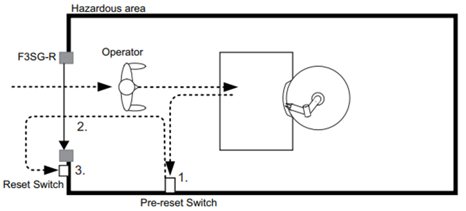
WITH the Pre-Reset function enabled, once the light curtains are triggered and the emergency stop engaged, in order to remove the emergency stop an operator must press the Pre-Reset switch, which is typically located inside the hazardous area, then trigger the light curtains by walking through them, and then pressing the reset switch, at which point the connected machinery can be activated again.
The below diagram illustrates this principle in action.
Procedure
Step 1 - Alignment
Ensure that the light curtains are installed and properly aligned.
In order to properly align the light curtains, first align the bottom ray, then the top ray. Blue LEDs on the bottom and top of the receiver unit will be lit to indicate the successful alignment of the appropriate ray.
Once both blue LEDs are lit, the green COM LED will also be lit, indicating alignment is complete.
Step 2 - DIP Switch Settings
On the bottom of both the receiver and the emitter light curtain units, there is a cover held in place by two screws. Behind this cover are the DIP switches for the light curtain's settings and functions.
The receiver unit has two banks of DIP switches. Ensure that these banks are set identically, otherwise the light curtains will enter a lockout mode.
To enable the Pre-Reset function, the receiver's DIP switches must be set as follows.
DIP switch 2 must be set to OFF
DIP switch 3 must be set to OFF.
DIP switch 4 must be set to ON.
DIP switches 5 and 6 must be both ON or both OFF.
DIP switch 8 must be set to OFF.
Step 3 - Wiring
Both the receiver and emitter light curtain units have multi-wore cables. The below image shows the wiring diagram for a PNP output.
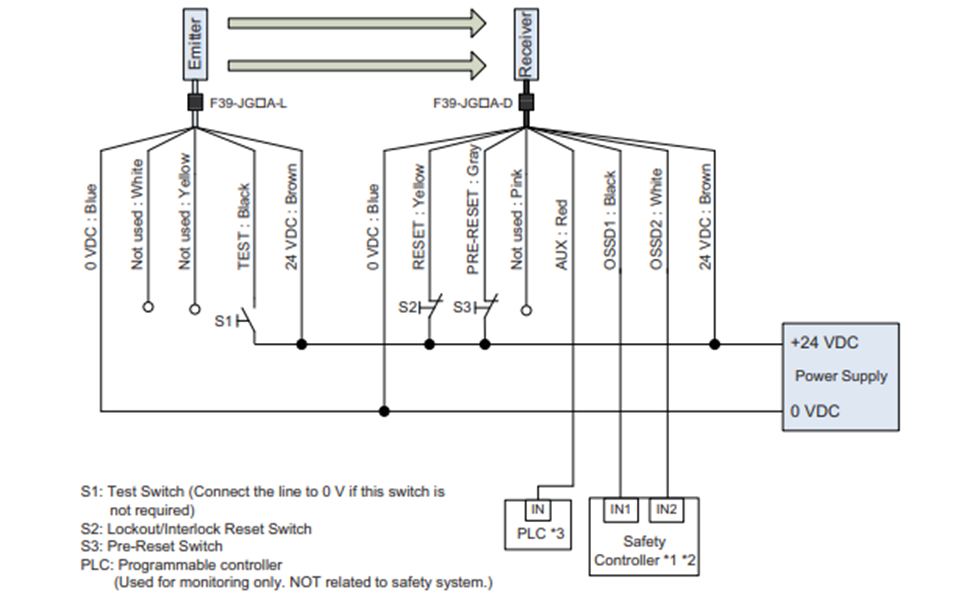
The emitter's TEST: Black wire is optional, and if not used, should be connected to the 0VDC rail.
The receiver's AUX: Red wire is for monitoring only, and should not be treated as a safety output.
Note that switches S2 (RESET) and S3 (PRE-RESET) are normally closed (NC) switches.
For the wiring configuration for an NPN output, see the below image.
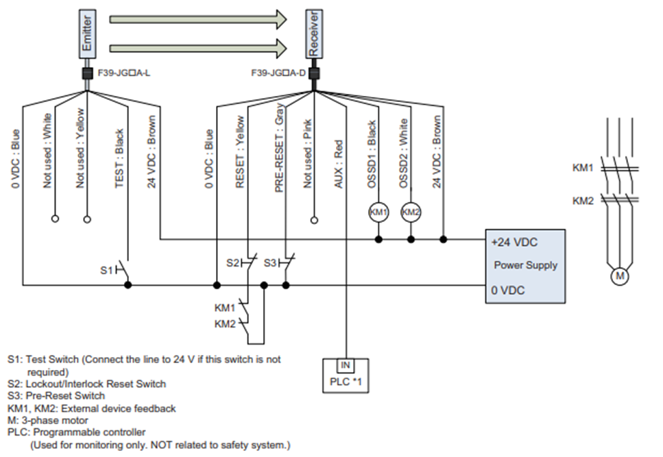
Note that for the NPN output configuration, if the emitter's TEST: Black wire is not used, it should be connected to the 24VDC rail.
Step 4 - Testing
To test the installed and configured safety light curtains with the Pre-Reset function enabled, apply the following procedure.
- Apply power to the light curtains.
- Check the indicators on the receiver unit, and ensure that the COM and EDM LEDs are green, the ON/OFF LED is red, and the INT-LK LED is flashing orange, in a pattern of two flashes followed by a pause. In this state, the safety light curtains have engaged their stop condition.
- Press and release the Pre-Reset switch.
- Block any of the beams of the safety light curtain by moving between the emitter and receiver units.
- Press and release the Reset switch. Note that this must be done within eight seconds of pressing and releasing the Pre-Reset switch.
- Check the indicators on the receiver unit, and ensure that the COM, EDM and ON/OFF LEDs are all green. In this state, the safety light curtains have disengaged their stop condition, allowing any connected devices to be started.
- Block any of the beams of the safety light curtain by moving between the emitter and receiver units. This will cause the safety light curtains to engage their stop condition.
At this point, the safety light curtains are correctly installed, configured, tested, and are ready to be used.
Additional Notes
If the reset process is interrupted, deviated from, or exceeds eight seconds between pushing the Pre-Reset and Reset switches, the process must be restarted from the step of pushing the Pre-Reset switch.
The push time of both switches must exceed 300ms.
The Pre-Reset function cannot be used in combination with blanking or muting functions.